

Time:2026-09-07
Energy overhead in industrial manufacturing facilities routinely accounts for 25% to 45% of total operating budgets, with uncontrolled high-bay illumination generating the largest baseline power waste. Modern commercial lighting control systems eliminate continuous 100% power usage by establishing a responsive, data-driven cyber-physical network that lowers electricity consumption, protects worker safety, and streamlines plant maintenance.
Deploying an enterprise-grade commercial lighting control system across an active manufacturing environment requires a robust multi-layer technical architecture. Rather than relying on localized manual switches or uncoordinated timer relays, modern industrial control networks integrate edge processing nodes, field-level environmental sensors, digital dimming protocols, and central Building Management System (BMS) gateways into a unified loop.
Environmental Telemetry Capture: Field sensors continually measure optical lux levels, human/machinery occupancy, and ambient operating temperatures across factory aisles and assembly lines.
Edge Logic Evaluation: Distributed area controllers evaluate raw sensor telemetry against programmed astronomical clocks, shift schedules, daylight harvesting curves, and emergency override inputs.
Control Output Transmission: Processed dimming commands are broadcast across wired digital buses or secure wireless mesh channels using standardized industrial protocols.
Driver Dynamic Execution: Dimmable LED drivers receive digital or analog control signals, executing smooth Pulse-Width Modulation (PWM) or Constant Current Reduction (CCR) dimming down to 0.1% power output.
Selecting the correct communications backbone determines signal latency, network scalability, and diagnostic capability across high-bay manufacturing plants.
| Network Protocol | Data Architecture | Wiring Requirements | Maximum Nodes / Segment | Diagnostic Reporting | Scalability & Range |
| DALI-2 (IEC 62386) | Bi-directional Digital Bus | 2-wire polarity-free control bus | 64 addresses per loop | Real-time power, lamp failure, temperature | Highly scalable via IP gateways |
| 0-10V Analog | Uni-directional Analog Voltage | 2-wire dedicated DC polarity pair | Channel-based (no individual address) | None (control only) | Limited by voltage drop (<30m) |
| BLE Mesh (Bluetooth) | Multi-hop Wireless Mesh | Wireless (power lines only) | Up to 32,767 nodes | Full device status and power telemetry | High density, auto-healing routing |
| BACnet/IP | Client-Server / Peer-to-Peer | Standard Cat5e/Cat6 Ethernet | Unlimited IP subnets | Comprehensive BMS integration | Enterprise-wide building integration |
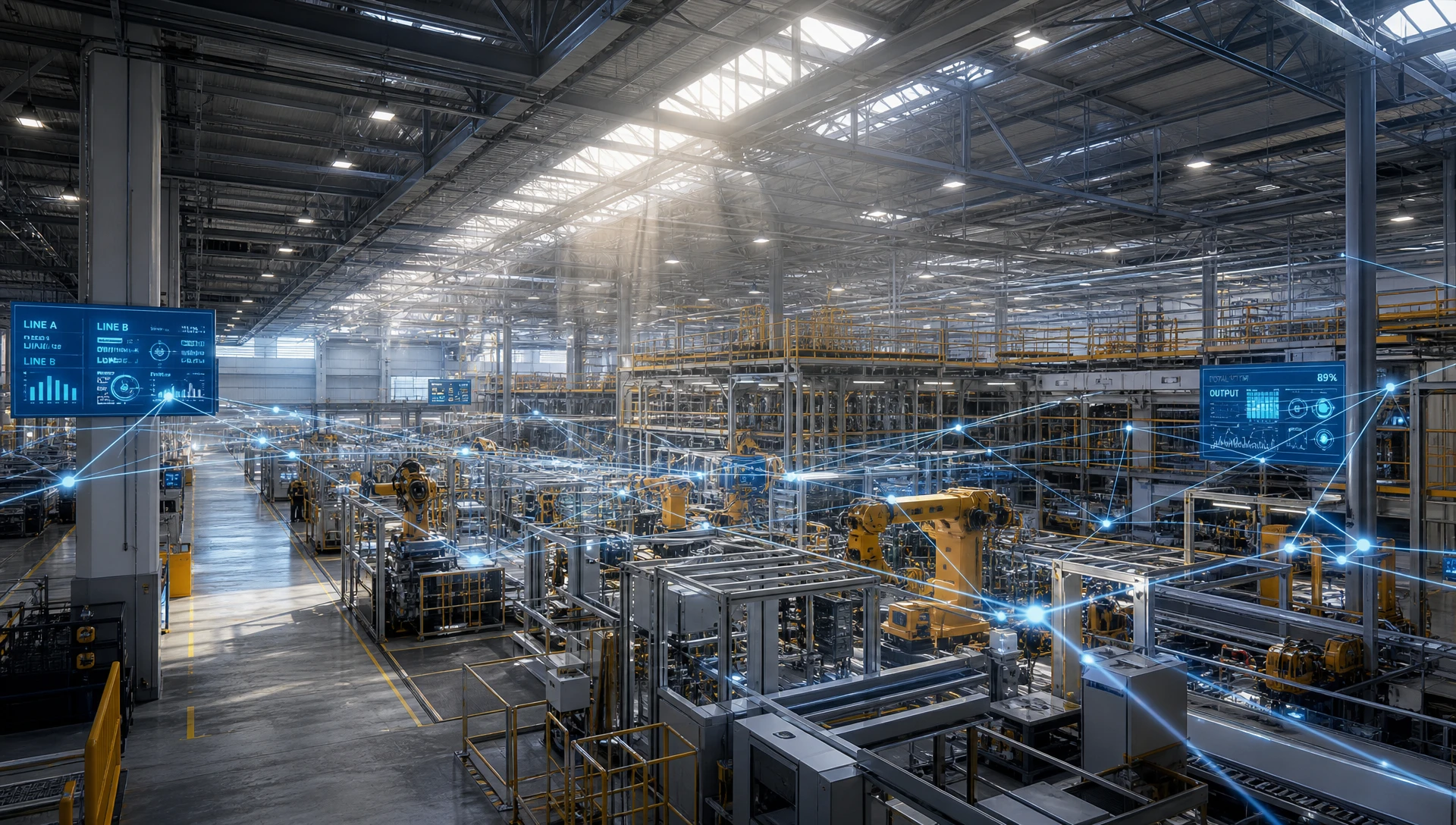
To maximize energy efficiency without compromising visual precision on assembly floors, commercial lighting control systems combine five key operational strategies into a unified automated schedule.
Optical sensors installed near high-bay skylights, saw-tooth roofs, or peripheral windows measure incoming natural light. The central controller dynamically reduces artificial luminaire power output to maintain a constant target illuminance (e.g., 500 Lux for general machining, 750 Lux for fine inspection).
High-frequency Microwave radar (5.8 GHz) or Passive Infrared (PIR) sensors monitor movement across aisleways, storage bays, and material handling zones. When a zone remains vacant beyond a preset hold time (e.g., 3 minutes), the system dims luminaires to a standby background output (10%–20%) rather than turning them completely off, ensuring safety while eliminating peak power waste.
New LED high-bay fixtures are frequently over-designed to compensate for lumen depreciation over their 100,000-hour lifespan. Task tuning establishes a permanent software ceiling on maximum fixture output—capping new fixtures at 75%–80% power—instantly saving energy while extending driver and LED diode operational lifespans.
During peak electrical utility pricing windows or facility-wide demand spikes, the commercial lighting control system receives automated signals from the energy management gateway. Non-critical lighting zones (such as warehouse aisles and shipping docks) automatically dim by 20% to 30%, shedding significant kilowatt load without interrupting active manufacturing processes.
Integrated real-time clocks automate facility-wide scene transitions aligned with plant shift schedules, cleaning routines, and weekend shutdowns. Facilities running multi-shift operations can transition lighting levels smoothly between active production hours and maintenance windows.
Integrating these strategies across expansive manufacturing footprints requires robust hardware infrastructure; plant engineers can explore our dedicated guide on
Predicting financial payback and system sizing for an industrial commercial lighting control system relies on rigorous mathematical modeling that accounts for daylight contribution, occupancy rates, task tuning caps, and HVAC thermal offsets.
Total illuminance (E_total) on an industrial work surface equals natural daylight contribution plus controlled artificial lighting output:
E_total = E_daylight + (P_dim * E_max)
Where:
E_total: Target surface illuminance (in Lux, e.g., 500 Lux).
E_daylight: Real-time daylight illuminance captured by photodiode sensors (in Lux).
P_dim: Controller dimming output ratio (ranging from 0.00 to 1.00).
E_max: Maximum illuminance generated by luminaires at 100% full power (in Lux).
To maintain constant target illuminance (E_target), the controller continually recalculates the dimming command:
P_dim = (E_target - E_daylight) / E_max
When E_daylight >= E_target, P_dim drops to 0.00 (or the minimum driver threshold), completely eliminating artificial lighting power consumption during bright sunlight hours.
To compute total annual kilowatt-hour (kWh) usage for a plant managed by commercial lighting control systems, engineers apply compounding reduction factors to baseline loads:
Energy_Annual = Sum [ (P_installed * N_fixtures * F_occupancy * F_daylight * F_trim * T_hours) / 1000 ]
Where:
Energy_Annual: Total annual lighting power consumption (kWh/year).
P_installed: Nominal full-power rating of each luminaire (in Watts).
N_fixtures: Total number of installed high-bay luminaires.
F_occupancy: Occupancy setback factor (active runtime ratio vs standby, e.g., 0.60).
F_daylight: Daylight harvesting factor (average artificial power ratio during daylight hours, e.g., 0.65).
F_trim: High-end task tuning factor (power cap ratio, e.g., 0.80).
T_hours: Total annual operational hours (e.g., 8,760 hours for 24/7 plants).
In climate-controlled manufacturing facilities, reducing lighting electrical power directly reduces the thermal load imposed on industrial HVAC chillers. Every kilowatt-hour of lighting energy eliminated reduces heat output into the space:
HVAC_Savings_kWh = Lighting_Savings_kWh / COP_cooling
Where:
COP_cooling: Coefficient of Performance of the facility's central cooling plant (typically 3.0 to 3.8 for industrial chillers).
Facility Parameters:
High-Bay Fixtures (N_fixtures): 2,000 units
Luminaire Power (P_installed): 240 Watts per unit
Facility Operation (T_hours): 8,760 hours/year (24/7/365 continuous operation)
Electricity Rate: $0.15 per kWh
HVAC Chiller COP (COP_cooling): 3.2
Baseline Uncontrolled Lighting Cost:
Energy_Base = (240 * 2,000 * 1.0 * 1.0 * 1.0 * 8,760) / 1000 = 4,204,800 kWh/year
Annual Lighting Cost = 4,204,800 kWh * $0.15 = $630,720 / year
Controlled Lighting Cost (Commercial Lighting Control System Deployed):
Applying realistic control factors: F_occupancy = 0.60, F_daylight = 0.65, F_trim = 0.80
Combined Control Factor = 0.60 * 0.65 * 0.80 = 0.312 (68.8% direct energy reduction)
Energy_Controlled = (240 * 2,000 * 0.312 * 8,760) / 1000 = 1,311,897.6 kWh/year
Annual Controlled Cost = 1,311,897.6 kWh * $0.15 = $196,784.64 / year
Direct & Indirect Financial Savings:
Direct Lighting Savings = 4,204,800 - 1,311,897.6 = 2,892,902.4 kWh/year ($433,935.36)
Indirect HVAC Cooling Savings = 2,892,902.4 / 3.2 = 904,032 kWh/year ($135,604.80)
Total Combined Annual Operating Savings = $433,935.36 + $135,604.80 = $569,540.16 / year
Industrial shop floors expose hardware to severe stress factors including elevated ambient temperatures, conductive dust particles, airborne oil mists, electromagnetic interference (EMI), and high vibration from overhead cranes. Selecting commercial lighting control hardware requires verifying strict mechanical and electrical compliance specifications.
| Industrial Zone | Primary Environmental Stress | Recommended Hardware Enclosure | Protocol & Electrical Protection | Sensor Technology |
| Heavy Machining & Tooling | Airborne oil mist, metallic dust, high vibration | IP67 sealed housing, IK10 impact rated | DALI-2 bus, 10kV/10kA surge arrestors | Dual-Tech (PIR + 5.8GHz Microwave) |
| High-Bay Warehousing (15m+) | Extreme mounting height, narrow movement corridors | IP65 housing, Zhaga Book 18 socket | BLE Mesh wireless node | Narrow-beam long-range PIR lens |
| Cold Storage Processing | Ambient temperatures down to -40°C, condensation | IP67 / NEMA 4X stainless mounting | Class P thermal drivers, silicon seals | Microwave radar with anti-frost optic |
| Electronics Cleanrooms | Static discharge, cleanroom particle constraints | Flush-mount IP60 panel, anti-static optic | 0-10V analog or DALI-2 isolated bus | Precision digital photodiode array |
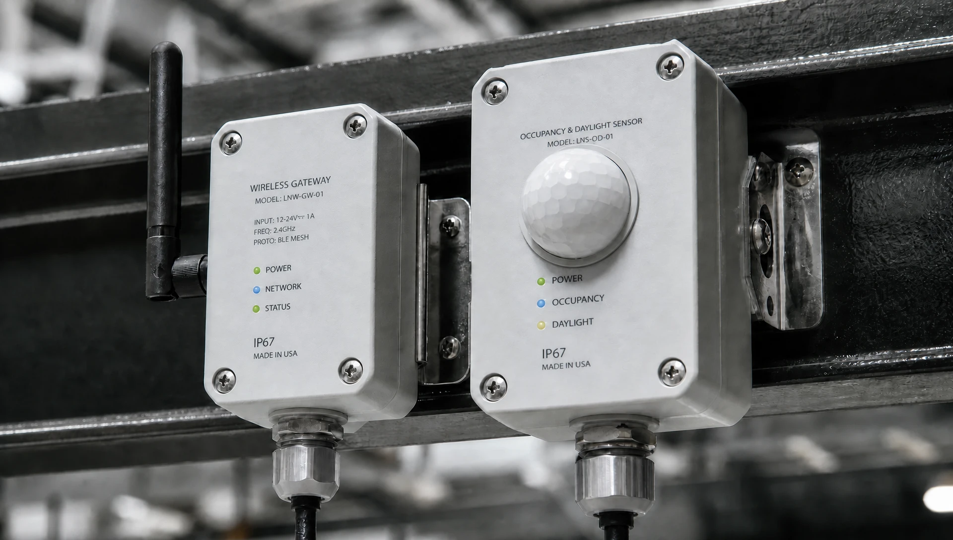
Inrush Current Protection: LED drivers draw high initial inrush currents (up to 80A for 200 microseconds) during power-on. Control relay modules must feature heavy-duty zero-crossing latching relays rated for 16A/20A inductive loads to prevent contact welding.
Socket Standardization: Modern intelligent high-bay luminaires utilize standardized Zhaga Book 18 or ANSI C136.41 7-pin NEMA twist-lock receptacles. This enables toolless installation and upgrading of wireless control nodes without opening fixture driver compartments.
Electromagnetic Compatibility (EMC): Industrial controllers must pass EN 55015 and FCC Part 15 Class A standards, incorporating differential and common-mode filter networks to prevent false sensor triggers near high-frequency induction furnaces or heavy motor VFDs.
Implementing an advanced commercial lighting control system ensures full compliance with international energy conservation codes, workplace illumination regulations, and green building certification requirements.
ASHRAE Standard 90.1 & IECC (International Energy Conservation Code):
Mandates automatic shutoff controls in 100% of warehouse aisles and open industrial spaces.
Requires independent continuous daylight-responsive controls in all primary side-lit and top-lit daylight zones.
Specifies maximum lighting power density (LPD) limits for industrial manufacturing categories.
California Title 24, Part 6:
Requires multi-level lighting control capabilities (at least 5 discrete step levels or continuous dimming).
Enforces mandatory Automatic Demand Response (ADR) client integration capable of receiving utility signal requests.
Mandates occupant sensing controls that drop fixture power by at least 50% during vacant periods in high-bay spaces.
EN 12464-1 (Lighting of Indoor Work Places - Europe):
Dictates strict visual ergonomic standards for industrial tasks (e.g., minimum 500 Lux maintained for welding, 750 Lux for fine electrical assembly).
Imposes limits on Unified Glare Rating (UGR < 19 for precision tasks, UGR < 22 for rough machining) and mandates Color Rendering Index (CRI > 80).
LEED v4.1 Building Operations and Maintenance (O+M):
Direct contribution toward Energy and Atmosphere (EA) Credit: Optimize Energy Performance (up to 18 points based on verified energy reduction).
Contributes toward Indoor Environmental Quality (EQ) Credit: Interior Lighting for providing individual task controllability and advanced scene controls.
Retrofitting or commissioning a commercial lighting control system in an operational factory requires a structured engineering roadmap to prevent production line shutdowns.
Phase 1: Photometric Audit & Baseline Assessment
Field engineers map existing lux levels across active work shifts, measure line voltage stability, catalog ceiling mounting heights, and document natural daylight entry points across plant zones.
Phase 2: Network Topology & Zoning Design
Define physical and logical control zones based on operational workflows (e.g., Receiving, Machining, Sub-Assembly, Packaging). Select network architecture (DALI-2 wired vs BLE Mesh wireless) and draft riser diagrams.
Phase 3: Physical Installation & Line Separation
Mount intelligent high-bay luminaires, wireless nodes, photocells, and gateways. Maintain strict physical separation between high-voltage AC power wiring (100V–480V) and low-voltage control signals (0-10V / DALI bus) to eliminate induced noise.
Phase 4: Address Provisioning & Group Binding
Perform auto-discovery of network nodes via commission software. Assign unique DALI short addresses or BLE mesh cryptographic network keys. Bind field sensors to local luminaire driver groups.
Phase 5: Sensor Threshold & PID Loop Calibration
Calibrate daylight harvesting photodiodes during nighttime (zero daylight baseline) and peak solar hours. Adjust closed-loop Proportional-Integral-Derivative (PID) dimming responsiveness to eliminate visible flicker or abrupt light changes.
Phase 6: Telemetry Verification & BMS Handover
Verify real-time power telemetry, fault reporting, and emergency scene overrides. Export commissioning reports and integrate gateway data points into the central facility BACnet/IP management console.
Evaluating the financial feasibility of commercial lighting control systems requires analyzing initial capital expenditure (CapEx) against long-term operational expenditure (OpEx) savings across a 10-year horizon.
Plant Size: 75,000 square meters heavy manufacturing facility
Luminaire Count: 2,000 units High-Bay Luminaires
Operating Hours: 8,760 hours/year (Continuous 24/7 operation)
Electricity Tariff: $0.15 per kWh
HVAC Cooling COP: 3.2
| Financial Metric | Legacy Metal Halide (400W) | Uncontrolled LED High Bay (240W) | Full Commercial Lighting Control System |
| Connected Load per Unit | 440W (incl. ballast) | 240W | 240W (74.88W effective average) |
| Total System Connected Load | 880 kW | 480 kW | 149.76 kW (Effective Average) |
| Annual Electricity Consumption | 7,708,800 kWh | 4,204,800 kWh | 1,311,897 kWh |
| Annual Direct Electricity Cost | $1,156,320 | $630,720 | $196,784 |
| Annual HVAC Cooling Cost Penalty | $361,350 | $197,100 | $61,495 |
| Annual Lamp & Ballast Maintenance | $75,000 | $12,000 | $2,500 |
| Total Annual Operational Cost | $1,592,670 | $839,820 | $260,779 |
| Initial Hardware & Installation CapEx | Baseline | $320,000 | $410,000 |
| 10-Year Total Operating Cost (OpEx) | $15,926,700 | $8,398,200 | $2,607,790 |
| 10-Year Total Cost of Ownership (TCO) | $15,926,700 | $8,718,200 | $3,017,790 |
| 10-Year Net Savings vs Uncontrolled LED | Baseline | Baseline | $5,700,410 |
Incremental CapEx for Smart Controls: $90,000 ($410,000 controlled system vs $320,000 uncontrolled LED retrofit).
Annual Operational Cost Reduction: $579,041 per year savings compared to uncontrolled LED high bays.
Simple Payback Period: 1.86 months (0.155 years).
10-Year Return on Investment (ROI): 6,233%.
Transitioning an industrial plant to an intelligent commercial lighting control architecture yields complete capital payback in under two months, unlocking multi-million dollar operational savings over the lifespan of the equipment.
LumiEasy industrial commercial lighting control systems utilize optically isolated DALI-2 bus transceivers and frequency-hopping spread spectrum (FHSS) BLE Mesh protocols. Hardware controllers incorporate differential filtering and 10kV surge suppressors, ensuring uninterrupted signal transmission near induction equipment, heavy VFD drives, and high-voltage distribution lines.
Yes. LumiEasy enterprise control gateways support native BACnet/IP, BACnet MS/TP, and Modbus TCP/RTU translation protocols. This allows facility managers to monitor real-time lighting power consumption, adjust global dimming schedules, and receive instant diagnostic fault alerts directly from their central BMS software interface.
LumiEasy commercial lighting control systems integrate UL 924 compliant emergency lighting transfer switches and DALI-2 Part 202 emergency battery units. Upon main utility power loss, local emergency controllers automatically bypass dimming commands, instantly driving designated emergency luminaires to 100% full brightness via central inverter or localized battery backup power.
Modernizing your manufacturing facility with an intelligent control infrastructure slashes electrical energy bills, lowers HVAC cooling loads, complies with global building codes, and protects operational continuity.
To review complete hardware data sheets, request photometrical layout simulations, or consult with our automation engineers,


)
)
)
)

+86 15899791249

+86 755 2955 3313


Address: Huafeng No.1 Science and Technology Park, Sanwei, Bao'an District, Shenzhen, Guangdong, China.
