

Time:2026-07-16
Industrial manufacturing complexes operate under strict regulatory oversight and extreme operational stress. Unlike commercial office spaces or retail environments, a heavy industrial facility—such as a chemical processing plant, automotive assembly factory, or steel foundry—presents unique hazards during a power outage or structural emergency. High-speed automated machinery, toxic chemical lines, and vast, windowless high-bay production floors turn a sudden blackout into a life-threatening crisis within seconds.
For facility engineers, environmental health and safety (EHS) directors, and plant managers, maintaining emergency lighting is not just a safety priority; it is a strict legal requirement. Traditional, unmonitored emergency backup lights that rely on manual inspection routines are no longer adequate for complex industrial environments. They frequently fail undetected due to battery degradation, extreme ambient heat, or component wear, exposing operations to severe safety risks and massive regulatory fines.
To mitigate these risks, modern industrial spaces are upgrading to automated, centralized architectures. Understanding the core emergency lighting control monitoring system requirements is essential for designing a robust system that ensures life safety, guarantees continuous compliance, and withstands harsh factory conditions.
Industrial emergency backup lighting is governed by strict international and regional safety codes. These regulations specify exactly how systems must behave when primary grid power fails. Designing an emergency control system requires full compliance with several key regulatory frame networks.
Published by the National Fire Protection Association, NFPA 101 sets the standard for emergency egress illumination across industrial facilities in North America.
Illumination Metrics: Emergency lighting systems must provide continuous illumination along the designated path of egress for a minimum of 90 minutes following a primary power failure. The initial illumination level must average at least 1 foot-candle (10.8 lux) along the floor path, and must never drop below 0.1 foot-candle (1.1 lux) at any single point.
Testing Mandates: Section 7.9.3 enforces strict testing intervals. Systems must undergo a monthly functional test—where the emergency lights are activated for a minimum of 30 seconds—and an annual full-duration test, which runs the system on battery power for the complete 90-minute period to confirm battery capacity.
These standards define the minimum execution metrics for emergency escape lighting systems in commercial and industrial workspaces.
Response Thresholds: The system must achieve 50% of its required light output within 5 seconds of a primary power failure, and reach 100% of its designated illumination level within 60 seconds.
Automated Logging: The codes mandate keeping an official, unalterable logbook. This log must record all system tests, component failures, battery replacement dates, and calibration values to demonstrate compliance during unexpected safety inspections.
Regulatory Compliance Alert: Manual inspection protocols rely on workers walking through the facility with clipboards to test individual fixtures. In a 50,000-square-meter plant, this process takes days, introduces human error, and leaves the facility vulnerable to non-compliance penalties between inspection cycles.
When designing a facility-wide emergency lighting network, engineers must choose between two primary structural approaches: monitored self-contained systems or centralized battery systems (CBS). Both configurations must satisfy the core monitoring requirements, but they distribute physical assets and power lines differently across the plant floor.
In this setup, each individual emergency light fixture contains its own internal battery backup pack, charging circuit, and intelligent control node. The fixtures link back to a central monitoring station via a dedicated digital communication bus or a secure wireless mesh network.
Failure Isolation: A primary benefit is localized fault isolation. If an individual fixture's battery pack degrades or its charging circuit fails, the damage is restricted to that single node. The remaining fixtures along the evacuation path continue to function normally.
Maintenance Profile: This configuration requires tracking hundreds or thousands of individual batteries scattered across high-bay ceilings. This increases physical component tracking needs and requires working at heights during routine replacements.
A centralized architecture consolidates the facility's backup batteries into a single, secure electrical room. This central inverter or DC battery bank connects directly to standard, non-battery emergency fixtures via dedicated, fire-rated branch distribution circuits.
Simplified Maintenance: Maintenance teams only need to service and balance one centralized battery bank located at ground level. This eliminates the need for lift equipment to replace batteries in high ceilings.
Line Loss Considerations: Because power travels from a single central room to fixtures throughout the plant, engineers must carefully manage localized line losses and voltage drops on long branch runs. This requires running thick, fire-resistant cabling to ensure distant fixtures receive adequate voltage during an emergency.
| Operational Matrix | Monitored Self-Contained Systems | Centralized Battery Systems (CBS) |
| Asset Location | Distributed inside each fixture | Consolidated in a dedicated utility room |
| Wiring Requirements | Standard wiring + digital communication bus | Specialized fire-rated high-gauge power lines |
| Single Point of Failure | Extremely low; isolated to individual fixtures | High; requires redundant inverter architectures |
| Battery Life Expectancy | 4 to 6 years (subject to ambient ceiling heat) | 10 to 15 years (housed in climate-controlled rooms) |
| Testing Architecture | Digital polling of individual nodes | Unified monitoring of the central inverter bus |
The central monitoring system must provide real-time visibility into every emergency fixture, control node, and backup battery power line across the facility.
Battery Diagnostics: The system must track voltage levels, charging currents, and internal temperature profiles for every battery asset. It should flag early signs of cell degradation before a battery fails a runtime test.
Driver and LED Status: The controller must monitor the electrical current draw of the LED drivers. If an LED string fails or a driver circuit opens, the system must instantly pinpoint the exact location of the faulty fixture on the plant floor.
Industrial systems cannot tolerate long switching delays. When main utility power fails, the control system must transition to backup power immediately.
Phase Failure Identification: The system must monitor all three phases of the primary distribution panel. If any single phase drops below 85% of its nominal voltage, the system must recognize a phase failure condition within 250 milliseconds.
Switching Execution: The emergency control loop must activate backup power lines and bring emergency fixtures to their required light output within 0.5 seconds of detection. This rapid transition prevents panic and ensures workers can safely navigate moving machinery.
Factory floors are harsh electrical environments filled with severe electromagnetic interference (EMI) from heavy machinery, variable frequency drives (VFDs), and high-voltage conduits.
Noise Suppression: The system's communication bus must use differential signaling, robust shielding, and optical isolation. This prevents high-voltage spikes and inductive noise from corrupting data packets or causing false emergency triggers.
Network Scalability: The control architecture must scale easily to support thousands of distinct network nodes. It should allow engineers to group fixtures into logical safety zones that map directly to the facility's evacuation routes.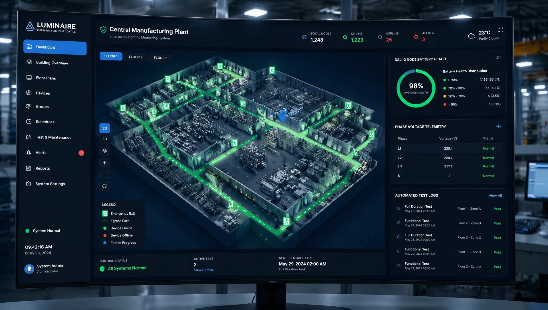
A failure in one part of the emergency network must never compromise the entire safety system.
Short-Circuit Protection: If an explosion, pipe burst, or structural collapse destroys an emergency light fixture and shorts out its supply wire, localized circuit protection must isolate that branch instantly.
System Integrity: By isolating the faulted branch, the system prevents the short circuit from tripping the main emergency breaker, ensuring the rest of the facility's backup lights remain fully operational.
The communication infrastructure connects individual emergency fixtures to the central automation engine. Selecting the right physical layer topology determines the network's data throughput, installation cost, and resistance to environmental noise.
DALI-2 is the leading open-standard protocol for modern commercial and industrial lighting control systems. The DALI-2 standard includes specific extensions (Part 202) that define device types for self-contained emergency lighting (Device Type 1).
Bi-Directional Communication: DALI uses a two-wire control bus that allows two-way communication between the central controller and individual fixtures. The controller can command specific fixtures to run functional tests, query battery health metrics, and retrieve real-time energy use data over standard, unshielded cabling.
Topology Flexibility: DALI buses support star, daisy-chain, or combined topologies without requiring terminating resistors. This flexibility simplifies routing through complex, high-bay factory roof structures.
For exceptionally large industrial spaces with long layout spans, standard serial networks like Modbus RTU running over RS-485 interfaces remain a popular choice.
Long-Distance Performance: RS-485 lines can extend up to 1,200 meters without requiring signal repeaters, making them ideal for massive logistics warehouses and heavy manufacturing plants.
Installation Discipline: RS-485 requires a strict daisy-chain layout with matched terminating resistors at both ends of the run to prevent signal reflections. Dropping branch lines off the main bus can degrade data quality, requiring careful planning during installation.
In retrofits or facilities with concrete structures where running new communication conduit is too expensive, industrial wireless mesh networks offer a viable alternative.
Self-Healing Redundancy: Wireless nodes form a decentralized mesh where each fixture acts as a signal repeater. If a large piece of machinery blocks one wireless path, the network automatically reroutes data packets through adjacent fixtures, ensuring continuous communication with the central controller.
Industrial Path Challenges: Heavy metal structures, overhead cranes, and high-frequency welding gear can disrupt wireless signals. Ensuring reliable performance requires thorough radio frequency (RF) site surveys and strategically placed high-gain directional antennas.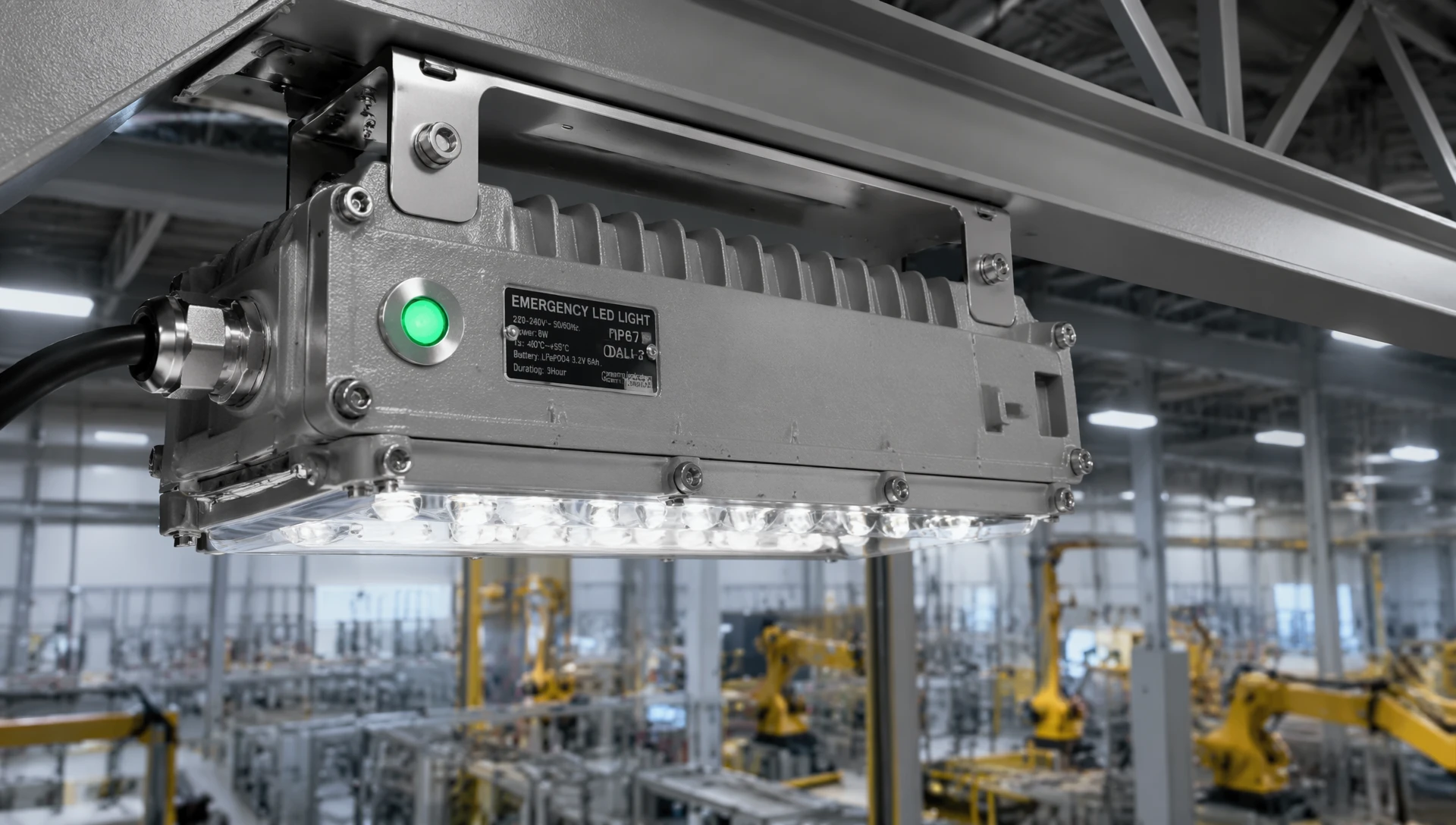
The primary operational advantage of an advanced emergency monitoring system is its ability to automate required safety testing. This eliminates manual labor costs and provides continuous verification of facility safety.
Every 30 days, the central automation controller automatically runs a functional test across the entire emergency lighting network. The system can be configured to test fixtures in alternating patterns, ensuring that adjacent fixtures are never tested at the same time. This keeps the facility protected if a real power failure occurs during a test.
During the 30-second test window, the internal controller switches the fixture to battery power and measures the current draw under load. The system logs these values to confirm the internal relay, driver, and LED array are operating within correct tolerances.
Once a year, the system schedules a comprehensive 90-minute full-duration test to verify total battery capacity. The system drops the primary charging voltage to simulate a full grid failure, forcing all emergency nodes to run entirely on their backup batteries.
The central controller monitors the discharge curve of every battery bank in real time. If a battery's voltage drops below the safe operating threshold before the 90-minute timer finishes, the system flags that specific asset as degraded, generates a high-priority maintenance ticket, and updates the compliance log.
An isolated emergency lighting network creates data silos that increase maintenance overhead. For optimal efficiency, the system should integrate cleanly with the facility's existing building management systems (BMS) and plant automation platforms.
Modern industrial controllers bridge lighting communication protocols like DALI with common industrial networks like BACnet/IP or Modbus TCP. This integration allows the main SCADA control room to track emergency safety metrics directly from their primary monitoring dashboards.
If an emergency battery in a remote compressor building fails, the alert pops up immediately on the plant engineer's master terminal, allowing maintenance teams to respond quickly.
The emergency lighting control network must interface directly with the facility's central Fire Alarm Control Panel (FACP). When the fire alarm system detects smoke or activates a sprinkler zone, it sends an overriding signal to the lighting controller via secure dry contacts or network commands.
The lighting system instantly responds by turning on all emergency lights at 100% brightness, bypassing any local wall switches or energy-saving dimming schedules. This ensures clear visibility along the entire evacuation route during a fire event.
To explore how intelligent network hardware combines emergency safety with daily energy efficiency, review our specialized guide on how to
Deploying a reliable, factory-wide emergency network requires a structured, step-by-step process from initial field testing through long-term maintenance.
Verify the unique physical conditions of the plant floor before specifying hardware. Check ambient temperature ranges near the ceiling—extreme heat will shorten battery life, requiring insulated enclosures or a centralized battery room layout. Map out heavy machinery locations to identify sources of electromagnetic noise, and plan shielded communication runs away from high-voltage lines.
Calculate expected line losses across all planned emergency branch circuits. Ensure that the wire gauge matches the length of the run so that the furthest fixtures receive stable voltage under full load.
Once installation teams mount the hardware, use the central monitoring software to discover and address every control node on the bus. Assign each fixture a unique digital address and group them into logical safety zones that correspond to the building's designated evacuation paths and exit points.
Run a complete system test to establish baseline performance metrics. Record initial charging currents, full-load battery voltages, and communication response times for every node. Save these baseline values into the central database to use as a reference point for future automated diagnostics.
Configure the system's automated testing schedules to run required monthly and annual checks. Set up encrypted compliance log storage on a secure local server or cloud platform, ensuring it generates tamper-proof reports that can be easily exported for fire marshals and safety auditors.
A1: No. Standard commercial emergency fixtures lack the heavy-duty housing required to withstand industrial environments. Industrial plants require rugged fixtures with IP66 or IP67 ratings to protect internal electronics and batteries from moisture, conductive dust, and corrosive chemicals. They also need robust vibration resistance to handle the constant movement of heavy plant machinery.
A2: The central control software manages testing algorithmically. During a scheduled test, the system commands the internal microprocessor to draw power from the battery while leaving the primary utility line active. If a real power outage occurs during a test, the system instantly cancels the test routine, bypasses all programming, and switches all fixtures to emergency fail-safe mode at maximum brightness.
A3: For older facilities, LumiEasy provides high-performance wireless mesh network control nodes that mount directly to existing emergency fixtures. These smart modules automatically link together to form a highly reliable, self-healing wireless network that communicates directly with a central gateway, eliminating the need to install expensive new data conduits through concrete or brick walls.
Building a fully compliant, reliable emergency lighting network requires high-grade hardware, intelligent software management, and deep technical expertise. Relying on outdated manual inspection routines introduces human error, increases maintenance costs, and leaves your facility exposed to regulatory liabilities and safety risks.
LumiEasy provides a complete line of industrial-grade emergency lighting controllers, intelligent monitoring networks, and automated compliance tracking systems built for heavy manufacturing environments. Our solutions feature wide operating temperature ratings, robust noise immunity, and seamless integration with existing industrial automation platforms, ensuring your plant remains safe and fully compliant under all conditions.
Do not wait for a critical power failure or an unexpected safety audit to discover weaknesses in your backup systems. Contact our engineering team today to review your plant layouts, discuss custom system requirements, or request a detailed project quote. Visit our official




+86 15899791249

+86 755 2955 3313


Address: Huafeng No.1 Science and Technology Park, Sanwei, Bao'an District, Shenzhen, Guangdong, China.
