

Time:2026-08-12
Industrial facilities, high-bay warehouses, and modern manufacturing plants face mounting pressure to reduce energy overhead while improving operational efficiency. Lighting accounts for up to 40% of total electrical consumption in commercial and industrial buildings. While upgrading to passive LED fixtures provides immediate energy relief, deploying Networked Lighting Controls (NLC) unlocks deep operational savings—often reducing lighting-related power consumption by 65% to 80%.
Installing an industrial smart lighting network requires a far more rigorous engineering approach than setting up residential or light commercial systems. Industrial deployments involve high-voltage branch circuits, complex fieldbus cabling, ambient electromagnetic
noise (EMI), extreme ceiling heights, and integration with Building Management Systems (BMS) via BACnet or Modbus.
This comprehensive how to connect smart lighting systems setup guide provides facility engineers, electrical contractors, and system integrators with a clear roadmap for planning, wiring, commissioning, and integrating robust industrial lighting networks.
Before installing hardware on a factory floor, engineering teams must evaluate physical and logical network topologies based on ceiling height, environment interference, and facility control requirements. The four primary architectures used in industrial smart lighting are Digital Addressable Lighting Interface (DALI-2/D4i), Analog 0-10V Control, Wireless Mesh Networks, and Power over Ethernet (PoE).
DALI-2 (IEC 62386) is the global open standard for bi-directional digital lighting control. A single DALI channel consists of two polarity-free control wires operating at a nominal 16V DC bus level.
Capacity: Supports up to 64 control gear (LED drivers) and 64 control devices (sensors/switches) per bus line.
Key Advantage: Individual device addressing. Every LED driver can be monitored, grouped, and dimmed independently without altering physical AC wiring.
Best Application: Medium-to-large factory floors, cleanrooms, and automated assembly plants requiring individual luminaire health diagnostics (DALI Parts 251, 252, and 253).
Analog 0-10V dimming uses a low-voltage DC signal varying between 0V (minimum light output or off state) and 10V (maximum brightness).
Capacity: Dictated by the current-sinking capacity of the controller (typically 20 to 50 drivers per zone channel).
Key Advantage: Straightforward installation, low component cost, and universal driver support.
Best Application: Small warehouses or uniform production bays requiring simple, single-zone group dimming without fixture-level feedback.
Wireless smart lighting utilizes 2.4 GHz RF communication where fixtures act as nodes, forming a self-healing mesh that routes data across the facility to central gateways.
Capacity: Hundreds to thousands of nodes per gateway cluster.
Key Advantage: Eliminates dedicated control wiring. Ideal for retrofit installations where pulling new control cables through concrete walls or high ceilings is cost-prohibitive.
Best Application: High-bay logistics centers, warehouse retrofits, and expansive industrial campuses.
PoE lighting delivers low-voltage DC power and high-speed data over standard Cat5e/Cat6 cabling using IEEE 802.3bt (Type 4, up to 90W per port) standards.
Capacity: Dedicated IP-addressable port per luminaire or small fixture cluster.
Key Advantage: Direct IT network convergence, native IP addressing per fixture, and complete elimination of high-voltage AC wiring at the fixture level.
Best Application: Modern smart factories, pharmaceutical laboratories, and high-tech manufacturing plants with unified IT/OT infrastructures.
| Feature / Metric | DALI-2 / D4i Digital Bus | 0-10V Analog Loop | Wireless Mesh (Zigbee / BLE) | Power over Ethernet (PoE) |
| Control Signal Type | Digital (Bi-directional) | Analog (Uni-directional) | Digital RF (Mesh) | Digital IP (Ethernet) |
| Max Cable Distance | 300m (using 1.5mm² wire) | 100m (due to voltage drop) | 10m–30m per node hop | 100m (Standard Cat6 limit) |
| Individual Addressing | Yes (64 per loop) | No (Zone level only) | Yes (Thousands per network) | Yes (Native IP per port) |
| Telemetry & Diagnostics | Yes (DALI Parts 251–253) | No | Yes (Device dependent) | Yes (Full IT telemetry) |
| Noise Susceptibility | Low (Differential signal) | Medium (Noise pickup) | Medium-High (RF obstacles) | Ultra-Low (Shielded Twisted) |
| Retrofit Ease | Moderate (Requires 2 wires) | Moderate (Requires 2 wires) | Extreme Ease (No control wires) | Complex (Requires Cat6 runs) |
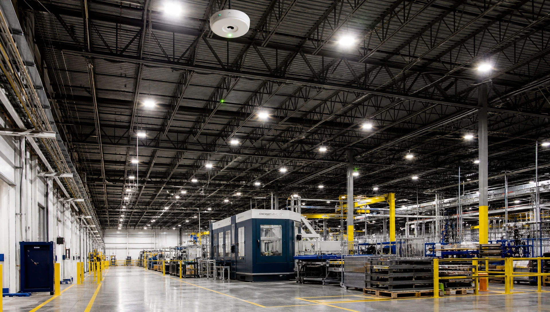
Commissioning errors are frequently traced back to oversights during pre-installation electrical calculations. Before pulling wire, engineers must confirm bus power limits, voltage drops, and cable specifications.
A DALI bus requires a dedicated power supply delivering nominally 16V DC (guaranteed 12.0V to 20.5V DC operating range). The total current drawn by all connected drivers and input devices on a single channel must never exceed 250 mA.
Formula:
Total Bus Current (I_total) = Sum of Driver Currents + Sum of Sensor Currents <= 250 mA
A standard DALI-2 LED driver consumes approximately 2 mA.
A DALI-2 multi-sensor (PIR occupancy + photodiode) consumes between 5 mA and 15 mA.
Design Example: 50 LED drivers (50 x 2 mA = 100 mA) + 6 multi-sensors (6 x 10 mA = 60 mA) = 160 mA total draw. This leaves a reliable 90 mA margin below the maximum 250 mA threshold.
For wired control buses, the maximum acceptable voltage drop along the control line is 2.0V. Wire cross-sections should follow these maximum run lengths:
0.5 mm² (20 AWG): Maximum cable run of 100 meters.
0.75 mm² (18 AWG): Maximum cable run of 150 meters.
1.5 mm² (15 AWG): Maximum cable run of 300 meters (Standard industrial engineering specification).
Engineering Note: While DALI control lines do not require shielded twisted pairs, running control cables directly alongside heavy AC lines or variable frequency drives (VFDs) can induce unwanted noise. Maintain a minimum separation of 30 cm from 480V/277V AC power lines when routing through industrial spaces.
Adhering to a structured hardware installation sequence ensures installer safety, signal integrity, and code compliance.
Perform Lockout/Tagout (LOTO): Isolate all 480V/277V or 230V AC distribution panels feeding the target installation bay.
Isolate Emergency Lines: If the smart control system manages emergency egress fixtures, verify that unswitched permanent AC live feeds are routed directly to emergency driver sense terminals.
Install Surge Protection Devices (SPD): Heavy industrial equipment causes frequent line surges. Install Class II (Type 2) SPDs providing at least 10 kV surge suppression at local distribution panels.
Connect main power lines (L, N, PE) to the driver input terminals. For control wiring, follow protocol-specific requirements:
DALI-2 / D4i Bus Connections: Connect the two control wires to the driver terminals marked DA/DA (or DA+/DA-). DALI lines are polarity-free. Daisy-chain control wires from fixture to fixture using line, star, or tree configurations. Ring topologies are strictly prohibited as they create signal timing loops.
0-10V Control Connections: Connect positive (typically purple) to DIM+ and negative (typically pink/gray) to DIM-. Maintain strict polarity. Reversing DIM+ and DIM- causes the driver to default to 100% output and ignore control signals.
High ceiling clearance in factories demands precise sensor optics:
High-Bay Optics: For mounting heights above 10 meters, select Passive Infrared (PIR) or microwave sensors equipped with narrow-angle Fresnel lenses. Wide-angle lenses installed at 12 meters fail to detect floor-level motion reliably.
Mitigating Microwave False Triggers: Keep Doppler microwave motion sensors at least 3 meters away from industrial ventilation fans or vibrating machinery to prevent false triggers.
Daylight Photodiode Placement: Position daylight harvesting sensors to measure light reflected from floor surfaces (closed-loop) or incoming natural sunlight through skylights (open-loop), avoiding direct exposure to adjacent light beams.
RS485 Line Termination: For gateways communicating via RS485 (BACnet MS/TP or Modbus RTU), install a 120-Ohm, 0.25-Watt resistor across the A and B data lines at both physical ends of the bus trunk.
Single-Point Shield Grounding: Connect cable braid shielding to ground at one end only (typically at the gateway enclosure). Grounding both ends creates ground loops that introduce data errors.
Software commissioning translates physical connections into an organized, automated control system.
Using a laptop connected via USB-to-DALI interface or a mobile commissioning application:
Run Discovery Search: The commissioning software broadcasts a system-wide query across the control bus or wireless mesh.
Assign Short Addresses: Unassigned DALI drivers are detected and allocated a unique Short Address between 0 and 63.
Perform Location Flashing: Send an IDENTIFY or BLINK command from the software. The targeted fixture flashes on the shop floor, allowing the engineer to map its virtual node to the CAD site plan.
Configure lighting parameters to match operational workflows across different facility areas:
Warehouse High-Bay Aisles: Set occupancy sensors to ramp lighting to 100% when a forklift enters, dimming to a 20% background level after 30 seconds of inactivity.
Manufacturing Workstations: Maintain constant task illumination (e.g., 500 to 750 Lux) during operating shifts, scheduling full shutoff during non-production hours.
Egress Pathways: Program designated fixtures to maintain a continuous 10% baseline output to satisfy facility safety egress requirements.
Daylight harvesting automatically dims artificial lights in response to natural daylight from skylights or windows.
Closed-Loop Calibration: Place a calibrated Lux meter at working height (typically 0.8 meters off the floor). Adjust the commissioning software setpoint until the meter reads the target light level (e.g., 500 Lux) under artificial light at night. Lock this setpoint into the controller’s PID logic.
LED luminaires are routinely over-specified to compensate for long-term lumen depreciation over an 80,000-hour service life. Brand-new fixtures running at 100% power often output excessive light.
High-End Trim: Cap maximum power output in software at 80% or 85%. This output reduction is virtually imperceptible to the human eye, but instantly reduces power consumption by 15% to 20% while extending driver operating life.
 5. Integrating Lighting Networks with BMS, SCADA & Cloud Platforms
Unifying lighting networks with central facility platforms—such as Building Management Systems (BMS), SCADA architectures, and ISO 50001 energy monitoring tools—creates a unified building control ecosystem.
Multi-protocol gateways map internal lighting registers to standard BACnet object types or Modbus holding registers for central management:
| Lighting Control Parameter | DALI Source Register | BACnet Object Type | Modbus Register Address | System Function |
| Zone Brightness Level | Direct Arc Power Level | Analog Output (AO) | Holding Register 40001 | Manual override / scene control |
| Occupancy Detection | DALI Part 303 | Binary Input (BI) | Discrete Input 10001 | Space utilization / HVAC triggers |
| Active Power (Watts) | DALI Part 252 (Bank 2) | Analog Input (AI) | Input Register 30001 | Real-time energy telemetry |
| Total Energy (kWh) | DALI Part 252 (Bank 2) | Analog Input (AI) | Input Register 30005 | Sub-metering & ISO 50001 audits |
| Driver Temperature | DALI Part 253 (Bank 3) | Analog Input (AI) | Input Register 30010 | Thermal health monitoring |
| Lamp Failure Status | DALI Part 253 (Bank 3) | Binary Input (BI) | Discrete Input 10005 | Automated work order creation |
HVAC Integration: When occupancy sensors report an unoccupied zone for more than 15 minutes, the BMS can automatically adjust airflow from VAV terminal units, saving heating and cooling energy.
Predictive Maintenance: Tracking driver temperature metrics (DALI Part 253) allows maintenance teams to identify overheating components and schedule repairs before catastrophic line failures occur.
When commissioning challenges arise, systematic troubleshooting isolates electrical, addressing, or RF protocol issues quickly.
| Issue / Error Symptom | Likely Root Cause | Engineering Diagnostic Procedure | Resolution |
| All DALI fixtures default to 100% and ignore commands | DALI bus voltage has dropped below 10.5V DC. | Check DC voltage across DA-DA terminals using a multimeter. | Replace or add a dedicated DALI bus power supply. Inspect for line shorts. |
| Fixture flickers during low-level dimming | Induced AC voltage noise on control signal line. | Measure AC voltage ripple on control lines using an oscilloscope (should be less than 0.5V). | Re-route control lines away from high-voltage AC cables or VFD drives. |
| Duplicate address errors during discovery | Multiple drivers sharing the same short address. | Send an INITIALISE command via commissioning software. | Re-run automatic short address assignment across the loop. |
| Wireless nodes lose connection during operation | RF signal attenuation caused by moving metal machinery or cranes. | Measure Received Signal Strength Indicator (RSSI) levels between nodes. | Install intermediate mesh repeaters or relocate gateways to maintain clear line-of-sight. |
| Occupancy sensors fail to detect floor movement | Sensor installed out of optics height spec or thermal blind spot. | Verify mounting height against manufacturer lens coverage diagrams. | Adjust PIR sensitivity threshold or swap to dual-technology (PIR + Ultrasonic) sensors. |
Before handing off a newly commissioned smart lighting system to facility management, verify all operational parameters against this engineering checklist:
Electrical Isolation & Surge Protection: Confirm all AC branch circuits are tagged and protected with Class II SPDs.
Bus Voltage Verification: Verify DALI bus voltage measures between 12.0V DC and 20.5V DC under full load.
Bus Current Margin: Ensure total connected bus current remains comfortably below 250 mA per channel.
Addressing Verification: Confirm all fixtures are individually addressed and correctly mapped on site plans.
High-End Trim Applied: Verify maximum output power is capped at 80%–85% across all general bays.
Sensor Timeout Configuration: Confirm occupancy sensor hold times are tuned to shift schedules.
Daylight Calibration: Verify daylight harvesting setpoints using a calibrated handheld Lux meter.
Line Termination: Ensure RS485 communication trunks have 120-Ohm termination resistors installed at line ends.
BMS Gateway Mapping: Confirm real-time power, energy, and fault points update accurately on the BMS interface.
Emergency Function Test: Test emergency lighting automated diagnostic schedules and battery self-test protocols.
Connecting an industrial smart lighting network requires a structured approach across hardware selection, field wiring, commissioning, and system integration. By choosing the right control architecture (DALI-2, 0-10V, Wireless Mesh, or PoE), adhering to wiring guidelines, and integrating control nodes into central BMS platforms, facility managers can achieve substantial operational savings while optimizing workspace lighting quality.
Whether you are designing a new high-bay production facility, retrofitting a logistics warehouse, or developing custom OEM control equipment, partnering with an experienced hardware manufacturer ensures long-term reliability.
Ready to integrate certified smart drivers, high-bay sensors, and networked control architectures into your next project? Contact our engineering team through the official
A1: Yes. DALI control signals run at a low data rate (1,200 baud) over a nominal 16V DC bus line. Standard 2-core mains-rated cables (such as 1.5 mm² NYM) can be routed alongside AC power leads in the same conduit without requiring specialized shielded twisted-pair wire.
A2: A single DALI-2 bus line supports up to 64 control gear (LED drivers). Multi-channel DALI gateways can manage 128, 256, or 512 fixtures across multiple channels. Wireless mesh gateways (such as Zigbee 3.0 or Bluetooth Mesh) can manage hundreds to thousands of individual nodes per network cluster.
A3: LumiEasy offers comprehensive technical support for industrial installations, including schematic design reviews, pre-programmed D4i driver configurations, high-bay sensor integration assistance, and BACnet/Modbus gateway setup support tailored to your project requirements.


)
)
)
)

+86 15899791249

+86 755 2955 3313


Address: Huafeng No.1 Science and Technology Park, Sanwei, Bao'an District, Shenzhen, Guangdong, China.
