

Time:2026-08-19
In modern industrial facilities, automated smart lighting systems represent one of the most effective strategies for reducing energy consumption, achieving sustainability targets, and ensuring workplace safety. However, the operational success of an automated industrial lighting deployment hinges on a critical yet frequently misunderstood technical metric: indoor lighting sensor range.
In high-bay manufacturing plants, automated logistics hubs, and cold storage warehouses, an incorrectly specified or miscalibrated sensor detection zone leads directly to operational friction. Under-specified sensor range creates dangerous "dark zones" where forklifts and personnel move undetected. Conversely, an oversized or uncalibrated detection envelope causes constant false triggering from ambient machinery, passing conveyor belts, or adjacent aisle movement—wasting thousands of kilowatt-hours annually.
This comprehensive technical guide provides plant facility managers, electrical engineers, and lighting OEMs with an authoritative breakdown of indoor lighting sensor range physics, sensor technology selection, high-ceiling spatial planning, field commissioning protocols, and energy ROI calculations.
To engineer a reliable automated lighting grid, facility teams must look beyond simple manufacturer datasheet claims and understand how sensor range is defined, measured, and attenuated in real-world factory environments.
Sensor detection coverage is not a uniform visual cone; it is a dynamic three-dimensional volume divided into two distinct sensitivity zones:
Tangential Detection Range: Movement across the sensor's optical field of view (perpendicular to the sensor lens). Passive Infrared (PIR) optical arrays are most sensitive to tangential movement because the moving target rapidly cuts across alternating thermal sensitivity facets in the Fresnel lens.
Radial Detection Range: Movement directly toward or away from the sensor. Radial sensitivity is typically 30% to 50% lower than tangential sensitivity because the target's thermal or frequency signature changes more gradually across the sensor's field.
In practical factory operations, a sensor mounted centrally on a ceiling projects a wide, high-sensitivity tangential envelope across the main aisle floor, whereas an approaching worker moving straight toward the sensor triggers the detection mechanism within a noticeably narrower radial boundary.
The effective ground-level coverage radius (R) is calculated as a direct mathematical function of mounting height (H) and the sensor's opening angle (θ):
Formula: R = H × tan(θ / 2)
When mounting height increases from a standard 3-meter (10 ft) commercial ceiling to a 14-meter (46 ft) high-bay industrial ceiling, the signal attenuation increases following the inverse-square law. Infrared thermal contrast decreases, and microwave Doppler reflections experience atmospheric and spatial dissipation. Therefore, specifying a sensor rated for a 12-meter range at ground level does not guarantee identical performance when mounted at a height of 12 meters.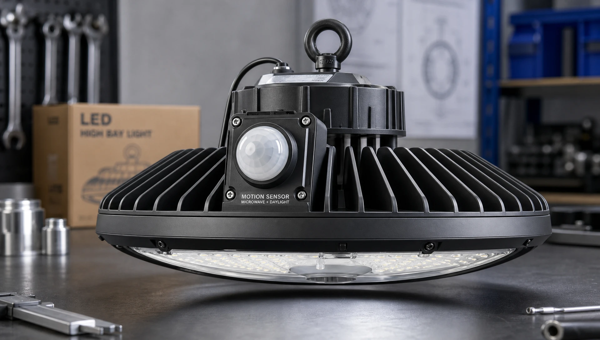
Selecting the optimal technology for a factory or warehouse requires matching the physical principles of the sensor to the environmental conditions of the facility.
PIR sensors operate passively by detecting far-infrared radiation (8–14 µm) emitted by warm objects relative to background ambient temperatures.
Strengths: Highly cost-effective, zero RF emission, immune to motion outside physical room barriers (walls, glass), ideal for defined aisle coverage when fitted with specialized high-bay optical Fresnel lenses.
Range Limitations: Susceptible to thermal crossover. When ambient factory temperatures approach human body temperature (35°C to 37°C / 95°F to 98.6°F), the thermal differential collapses, drastically reducing detection range by up to 60%.
Microwave sensors actively emit high-frequency electromagnetic waves (5.8 GHz or 24 GHz) and measure the Doppler shift of reflected signals.
Strengths: Exceptional range consistency across all ambient temperatures, high sensitivity to minute motion (e.g., fine hand movements at assembly workstations), capable of sensing motion through non-metallic barriers (plastic curtains, glass, drywall).
Range Limitations: Highly sensitive to industrial background noise. Uncalibrated microwave range can penetrate thin partitions or rack structures, causing lights in unoccupied adjacent aisles to turn on unexpectedly.
Dual-tech sensors combine PIR and Microwave detectors into a single unit utilizing digital signal processing (DSP) logic.
Activation Logic: Initial trigger requires both PIR (thermal) and Microwave (Doppler) confirmation to initiate lighting. Once active, maintaining illumination requires detection by either technology.
Range Advantage: Provides the widest reliable detection footprint in hostile factory environments (e.g., spaces with heavy HVAC airflow, ambient thermal fluctuations, or heavy machine vibration) while virtually eliminating false trips.
| Technical Metric | High-Bay PIR Sensor | 5.8 GHz Microwave Sensor | 24 GHz High-Frequency Radar | Dual-Tech (PIR + Radar) |
| Max Mounting Height | 12 to 15 m (39 to 49 ft) | 8 to 12 m (26 to 39 ft) | 12 to 15 m (39 to 49 ft) | 12 to 15 m (39 to 49 ft) |
| Max Detection Diameter | 18 to 24 m (59 to 78 ft) | 16 to 20 m (52 to 65 ft) | 20 to 28 m (65 to 91 ft) | 20 to 25 m (65 to 82 ft) |
| Thermal Sensitivity | High (Degrades above 30°C) | None (Stable -20°C to 60°C) | None (Stable -20°C to 60°C) | Medium (Mitigated by Radar) |
| Airflow / Draft Immunity | High | Low (Air turbulence triggers) | Medium | Extremely High |
| Barrier Penetration | None (Direct line of sight) | High (Penetrates wood/glass) | Controlled (Low penetration) | None for initial start |
| False Trigger Rate | Low | Moderate to High | Low to Moderate | Lowest (< 0.1%) |
Sensor range requirements vary significantly between industrial facility layout types. Applying low-bay commercial sensor profiles to industrial facilities is a primary root cause of smart lighting project failures.
High-density warehouse aisles create a severe masking effect. Racking structures reaching heights of 10 to 14 meters physically block wide-angle detection cones.
Standard circular coverage lenses project a wide 360-degree cone, casting most of the sensing energy directly onto the tops of steel racking. Industrial high-bay sensors overcome this by using specialized linear mask or aisle lenses that reshape the detection footprint into an elongated oval envelope (e.g., 5 meters wide by 20 meters long).
To ensure forklift drivers approaching an aisle intersection at 15 km/h (9.3 mph) experience instant light activation, sensors must be positioned at aisle entry heads with detection zones extending 3 to 4 meters beyond the rack face into the main transit corridor.
Heavy manufacturing halls require broad, overlapping coverage patterns to accommodate complex machinery layouts and variable worker movement.
Blind Spot Mitigation: Machinery, overhead cranes, and ventilation ducting create physical line-of-sight obstructions for PIR sensors. Facility engineers must map physical shadow zones and utilize overlapping detection grids where adjacent sensor patterns intersect by a minimum of 15% to 20%.
Vibration and Interference Filtering: Stamping presses, CNC equipment, and heavy conveyor motors generate low-frequency mechanical vibrations. Sensor mounting hardware must be structurally decoupled from vibrating cable trays or luminaire housings, or calibrated using digital threshold filtering (such as zero-cross detection and adjustable micro-hold times).
Engineers must account for several environmental variables that attenuate indoor lighting sensor range in industrial facilities:
PIR sensor detection range is governed by the Delta Temperature (Delta T) between the human body (approximately 37°C) and background ambient surfaces.
Formula: Delta T = |T_target - T_ambient|
Winter Conditions (T_ambient = 10°C): Delta T = 27°C. Signal-to-noise ratio is exceptionally high; detection range reaches 100% to 110% of rated specification.
Summer Peak (T_ambient = 35°C): Delta T = 2°C. Thermal contrast drops significantly. Without automatic digital temperature compensation circuits, effective PIR range can drop from 20 meters down to less than 8 meters.
A sensor's effective coverage zone varies based on the moving object's surface area, velocity, and material composition:
Pedestrian Personnel (0.5 to 1.5 m/s): Smaller cross-sectional area and thermal mass require higher sensor gain settings to achieve full range.
Industrial Forklifts (3.0 to 5.0 m/s): Large metallic footprint and warm engine bay/battery pack are easily detected at maximum range distances. However, the high speed requires extending the range forward to compensate for system response time (luminaire driver startup time + sensor processing delay).
As mounting height increases, the physical signal strength hitting the sensor plane drops. Use the following practical engineering correction factors when calculating net indoor lighting sensor range:
3 m to 6 m (10 - 20 ft): Multiplier = 1.00 (Standard Datasheet Rating)
8 m (26 ft): Multiplier = 0.88
10 m (33 ft): Multiplier = 0.75
12 m (39 ft): Multiplier = 0.62
15 m (49 ft): Multiplier = 0.50 (Requires Specialized High-Bay Lens)
Designing an industrial lighting control plan requires a step-by-step methodology to eliminate blind spots, ensure workplace safety, and maximize energy conservation.
Map all architectural features, including ceiling structural grid lines, HVAC ducting, crane rail paths, and high-density racking locations. Identify ambient operating parameters (temperature ranges, humidity, mechanical vibration sources).
Choose PIR for defined high-bay aisles where thermal contrast is stable and zero barrier penetration is mandatory. Specify 24 GHz Radar or Dual-Technology sensors for open manufacturing bays, cold storage facilities, or spaces with high ambient thermal fluctuation.
Apply height and thermal attenuation multipliers to the sensor datasheet specifications. Calculate the net ground coverage diameter (D_net):
Formula: D_net = D_rated × K_height × K_temp
Space sensor nodes across the floor plan ensuring adjacent detection boundaries overlap by 15% to 20%. For comprehensive insights into spatial mapping principles and how modern digital interfaces optimize coverage zones, refer to this detailed technical guide on
Industrial sensors should interface directly with standardized digital lighting control protocols such as DALI-2 (IEC 62386 Part 303 / 304) or Zhaga Book 18 / D4i.
By utilizing standardized Zhaga Book 18 low-voltage sockets on high-bay LED luminaires, plant operators can mechanically mount smart sensor nodes with a simple twist-lock connection. The sensor connects directly to the internal DALI D4i driver via auxiliary DC power and bidirectional communication buses.
This digital coupling allows physical sensor detection to be decoupled from fixture wiring. For example, a single sensor detecting motion in Aisle 1 can instantly transmit a digital command across the DALI bus to illuminate Aisles 1, 2, and adjacent staging zones simultaneously, while streaming real-time operational telemetry back to the central Building Management System (BMS).
Optimizing indoor lighting sensor range directly impacts facility operating costs. Installing standalone high-bay LED luminaires without smart controls yields baseline LED energy savings (typically 40% to 50% compared to legacy metal halide or T5 fluorescent systems). However, integrating precise, range-optimized sensor control unlocks an additional 30% to 55% energy reduction through motion-based task tuning and daylight harvesting.
Facility Profile:
Facility Type: 24/7 Logistics Distribution Center (20,000 square meters / 215,000 sq.ft)
Ceiling Height: 12 meters (39 ft)
Luminaire Count: 500 High-Bay LED Fixtures (150 W per fixture)
Total Installed Load: 75 kW
Electricity Tariff: $0.15 per kWh
| Operational Strategy | Annual Energy Consumption | Annual Electricity Cost |
| Strategy A: Uncontrolled LED (100% Always ON) | 657,000 kWh | $98,550 |
| Strategy B: Basic Sensor Control (Uncalibrated Range) | 361,350 kWh | $54,202 |
| Strategy C: Optimized D4i Range & Multi-Level Dimming | 216,810 kWh | $32,521 |
Strategy A (Uncontrolled LED): 75 kW × 8,760 hours = 657,000 kWh/year → $98,550 / year
Strategy B (Basic Sensor Control): Due to false triggering and non-optimized hold times, lights remain at full power 55% of the time → 361,350 kWh/year → $54,202 / year
Strategy C (Precision D4i Sensor Grid): Utilizes linear high-bay aisle optics, 24 GHz radar precision, and background dimming (10% standby during unoccupied periods). Lights operate at full power only during actual occupancy (25% of total time) → 216,810 kWh/year → $32,521 / year
Net Financial Gain:
Optimizing sensor range and control logic saves an additional $21,681 per year over basic sensor control, achieving full hardware payback on sensor installation within 7.5 months.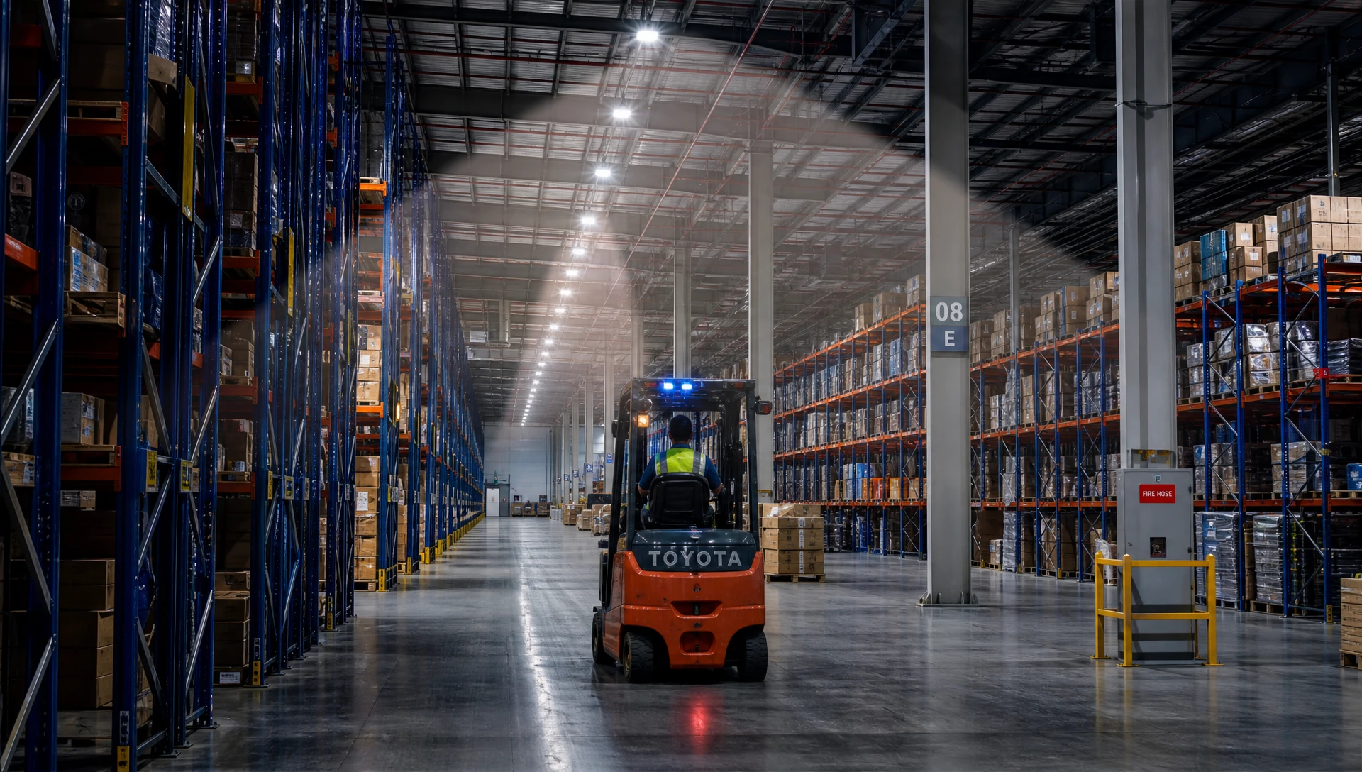
When industrial lighting control systems behave unexpectedly, field technicians can use the following diagnostic framework to identify and resolve range-related issues:
Root Cause A (Microwave/Radar): Sensitivity set too high; microwave signals penetrating thin partitions, glass, or plastic rack dividers.
Remedy: Reduce microwave detection threshold parameter via digital commissioning app or DIP switches. Upgrade to 24 GHz radar sensors with tighter field boundary control.
Root Cause B (PIR): High-velocity warm air streams from overhead unit heaters entering the PIR thermal optics field.
Remedy: Re-aim sensor optics away from HVAC discharge louvers or switch to Dual-Tech (PIR + Radar) sensing logic.
Root Cause A: Sensor mounted too deep within the rack aisle, masking the radial detection cone from cross-aisle traffic.
Remedy: Relocate the entry-head sensor node 0.5 to 1.0 meter outward toward the main transit aisle, or apply an aisle-extension optical lens.
Root Cause B: Thermal crossover during high ambient summer temperatures reducing PIR sensitivity.
Remedy: Enable automatic thermal threshold compensation in the sensor software, or increase PIR signal gain.
Root Cause: Micro-motion (assembly line hand work, seated desk work) falling below the sensor's sensitivity threshold at high mounting heights.
Remedy: Lower the primary sensor, add auxiliary low-bay secondary motion sensors at the workstation level, or adjust hold-time parameters from 30 seconds to 5 or 10 minutes.
At a mounting height of 12 meters, high-bay PIR sensors with specialized optical lenses typically provide a ground coverage diameter of 18 to 24 meters, while 24 GHz radar sensors achieve coverage diameters up to 28 meters. LumiEasy specifies precise height-attenuation profiles for every industrial sensor model to guarantee zero blind spots in high-ceiling environments.
PIR sensors rely on thermal contrast between moving objects and the surrounding environment. When ambient factory temperatures rise above 30°C (86°F), thermal contrast decreases, reducing standard PIR detection range by 30% to 60%. LumiEasy addresses this by integrating automatic temperature compensation circuits and offering 24 GHz microwave/radar alternatives that remain unaffected by ambient temperature swings.
LumiEasy high-bay sensors utilize specialized linear aisle lenses and advanced 24 GHz radar technology designed specifically for narrow, high-density storage environments. By shaping the detection footprint into an elongated oval and supporting DALI-2/D4i group mapping, LumiEasy sensors detect approaching traffic at aisle entrances before personnel or machinery enter, ensuring full illumination ahead of motion.
Optimizing indoor lighting sensor range is a vital engineering requirement for modern industrial facilities. By carefully matching sensor technology (PIR, Radar, or Dual-Tech) to ceiling heights, spatial layouts, and environmental conditions, facility managers can eliminate dark zones, enhance operational safety, and maximize energy savings. Digital integration via standardized DALI-2 and D4i architectures further transforms standalone lighting into a dynamic, data-driven industrial asset.
To evaluate your facility’s smart lighting infrastructure, request custom sensor layout engineering, or explore high-performance industrial sensor solutions,


)
)
)
)

+86 15899791249

+86 755 2955 3313


Address: Huafeng No.1 Science and Technology Park, Sanwei, Bao'an District, Shenzhen, Guangdong, China.
