

Time:2026-07-13
Industrial manufacturing facilities are experiencing an unprecedented transformation driven by data. As corporate ESG mandates tighten and global energy costs fluctuate, factory managers can no longer rely on broad estimations of utility consumption. Legacy building automation systems often group entire production wings under a single sub-meter, obscuring localized waste and preventing facilities from qualifying for premium utility rebates.
The adoption of Luminaire-Level Lighting Control (LLLC) systems addresses this challenge by embedding dedicated sensors, wireless transceivers, and intelligent microprocessors into every individual high-bay luminaire. However, the true value of an LLLC deployment does not lie in its physical hardware, but in its ability to securely extract, normalize, and transmit granular power metrics.
Understanding the underlying lllc energy reporting data collection protocols is essential for plant engineers, systems integrators, and procurement directors tasked with turning factory illumination systems into verified, audit-ready energy data hubs.
To appreciate why fixture-level data protocols matter, it is necessary to contrast LLLC architecture with traditional Networked Lighting Controls (NLC). Traditional NLC setups rely on a centralized or zone-level controller that distributes commands to an entire loop or circuit of dimmable LED fixtures. While effective for basic scheduling and bulk dimming, the zone controller only records the total energy consumption of that specific branch circuit. It cannot isolate an individual luminaire that may be malfunctioning or burning excess energy due to a localized sensor failure.
LLLC reverses this paradigm by distributing processing power directly to the edge. Each luminaire operates as an autonomous asset. Inside a modern industrial LLLC luminaire, an integrated sensor pod tracks occupancy, ambient daylight levels, and temperature, while the LED driver continuously monitors internal electrical characteristics.
By shifting control and telemetry collection to individual fixtures, the facility gains access to thousands of localized data streams. The critical challenge then shifts to network architecture: how does the system collect these micro-packets of energy data across a 500,000 square-foot production floor without degrading network bandwidth or exposing the facility to cyber risks? The solution requires choosing and implementing the correct data collection and transmission protocols.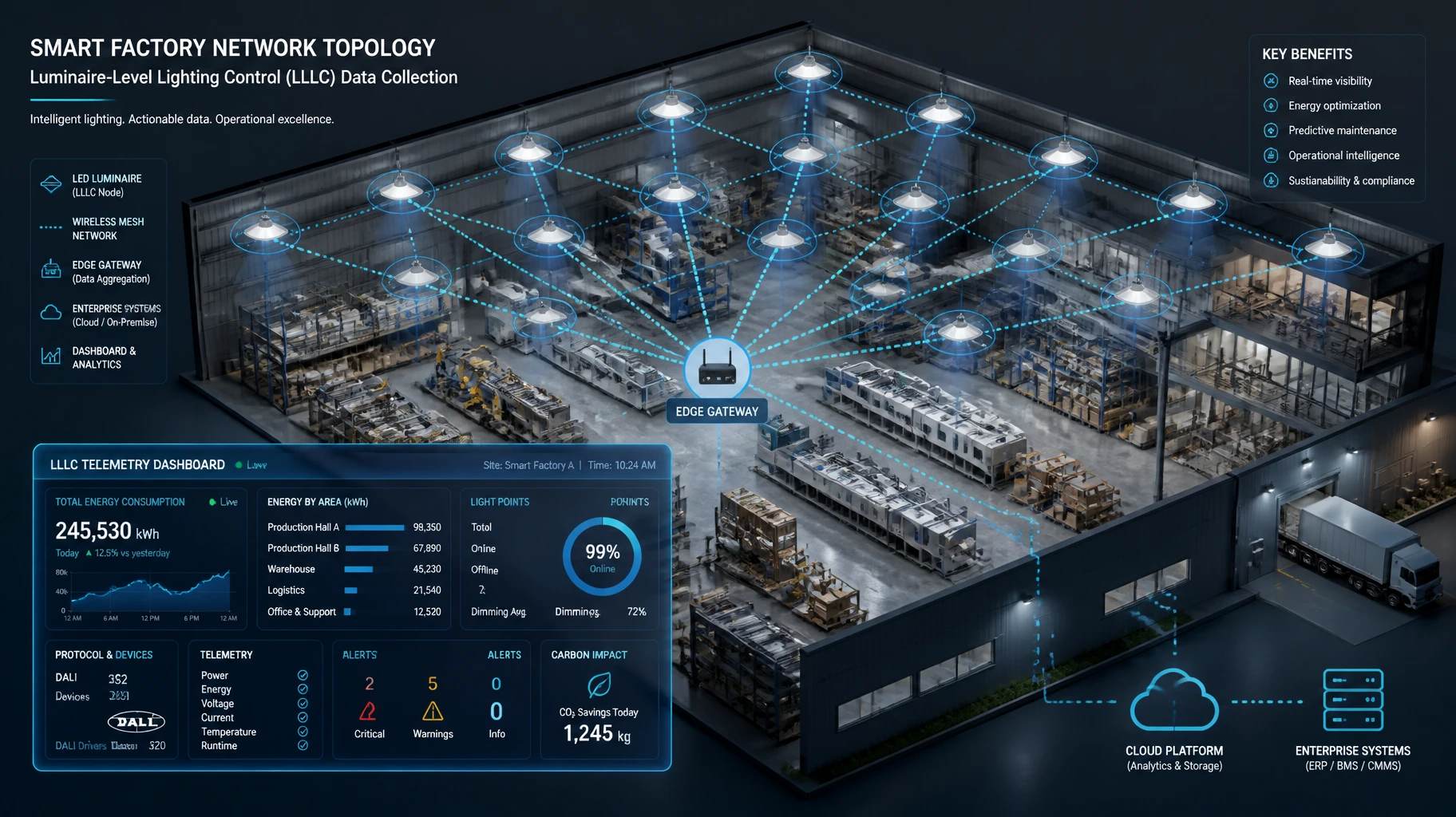
When deploying an enterprise LLLC network, data collection occurs in two primary stages:
Intra-luminaire communication (from the driver components to the integrated wireless node/transceiver)
Inter-luminaire communication (from individual fixtures across the wireless or wired mesh network to the central edge gateway)
Within the physical luminaire housing, the standardized interface between the intelligent LED driver and the wireless control node relies heavily on the Digital Addressable Lighting Interface (DALI) standard—specifically DALI Part 252 and DALI Part 253.
Before the introduction of these standards, drivers recorded energy data using proprietary formats, requiring custom software configurations for different hardware brands. DALI Part 252 establishes a standard data structure for storing energy and power metrics directly within the driver's memory banks. The integrated control node queries these standardized memory locations using a uniform command structure to extract specific metrics:
Memory Bank 14 (DALI Part 252): Stores active energy (kWh), active power (W), apparent energy (kVAh), apparent power (VA), and RMS voltage and current.
Memory Bank 15 (DALI Part 253): Gathers operational diagnostics, including total luminaire operating hours, driver thermal thresholds, and LED module failure counters.
This standardized structural layout ensures that regardless of who manufactures the underlying LED driver components, the wireless control node can read and package the telemetry data uniformly.
For industrial facilities operating across North America, ANSI C136.52 defines the standard for architectural and structural extensions to the ubiquitous 7-pin photocell receptacle layout. This protocol details the digital communication interface between a control node and a luminaire's internal driver, mandating strict levels of energy metering accuracy.
Under ANSI C136.52 guidelines, compliant drivers must provide revenue-grade or near-revenue-grade metering accuracy (typically within a 1.0% to 2.0% margin of error). This degree of accuracy is crucial for heavy industrial sites because utility providers frequently require verified ANSI-compliant data logs before issuing custom utility rebates or approving demand-response participation models.
Once the wireless control node extracts DALI Part 252 or ANSI C136.52 metrics from the driver, it packages this data into a wireless transport protocol to send across the facility floor. Industrial environments typically leverage one of two major wireless mesh protocols:
Bluetooth Mesh uses a managed flooding architecture to route data packets across vast distances. Instead of relying on specific routing paths that can be blocked by overhead cranes or heavy machinery, Bluetooth Mesh broadcasts data packets across multiple channels simultaneously.
For energy reporting, Bluetooth Mesh defines standard Mesh Model profiles specifically for lighting and sensor data. The energy telemetry is wrapped in a compact, 11-byte payload containing the absolute energy counter value, ensuring high-frequency reporting does not clog the 2.4 GHz wireless spectrum.
Zigbee Pro utilizes a routing table approach where data packets travel along pre-determined node-to-node pathways to reach the central gateway. While highly efficient in clear lines of sight, if a major physical obstruction moves into the factory pathway, the network must execute a "self-healing" routing update, which can temporarily delay data packet delivery.
Zigbee handles energy telemetry through the Zigbee Smart Energy (SE) Profile, which supports advanced encryption and comprehensive utility-grade metering attributes.
Converting raw electrical pulses into clean, audit-ready data tables requires a structured processing pipeline. Because an industrial facility may contain thousands of LLLC nodes, the central system must handle high volumes of incoming data without dropping packets or corrupting the time-series database.
Implementing robust data collection protocols is also essential for meeting global energy efficiency certifications and regulatory frameworks. Utility companies and regional governments have moved away from prescriptive rebate structures toward performance-based validation systems.
The DesignLights Consortium (DLC) maintains stringent technical requirements for its Qualified Products List (QPL). To achieve a DLC V5.1 listing under the Networked Lighting Controls category, an LLLC platform must prove it possesses native energy reporting capabilities at the system or zonal level, with fixture-level reporting heavily preferred for custom incentive tiers.
Systems that deploy standardized protocols like DALI Part 252 easily satisfy DLC validation rules because they provide verifiable, granular logs of actual power consumption rather than mathematical estimates based on dimming percentages. This distinction is critical: if a system merely estimates energy use based on an assumed driver curve, it often fails to qualify for the highest tiers of utility financial incentives.
Modern commercial building codes demand precise control and monitoring of lighting power densities. California’s Title 24 (Part 6) and global standards like ASHRAE 90.1 mandate comprehensive lighting controls, daylight harvesting, and real-time demand-response capabilities.
By leveraging native LLLC protocols, the system records how lighting levels automatically adjust in response to natural light availability. This data provides building inspectors and compliance officers with unalterable proof that the facility is adhering to its legal energy-use limitations.
Heavy industrial manufacturing floors present challenging RF environments for wireless data collection. Automated CNC machines, high-frequency arc welding stations, and massive overhead steel cranes generate significant electromagnetic interference (EMI) and multi-path fading that can disrupt wireless communication.
To maintain stable data collection across these challenging settings, industrial-grade LLLC nodes use several advanced hardware and software techniques:
Channel Hopping Spread Spectrum (FHSS): Wireless systems alternate across dozens of discrete frequency channels hundreds of times per second. If an arc welder creates a temporary burst of noise on one frequency band, the data packet is instantly retransmitted on a clear, adjacent channel without data loss.
Localized Sub-GHz Fallbacks: For facilities with dense concrete walls or deep underground structural layouts, systems may drop back to sub-GHz wireless protocols (such as 868 MHz or 915 MHz). These lower frequencies feature longer wavelengths that travel through physical obstacles much more effectively than standard 2.4 GHz signals.
Data Buffering at the Edge: If a localized network disruption isolates a group of luminaires, the internal memory cache within each node stores up to 48 hours of continuous energy data. Once the network heals, the nodes upload their buffered records chronologically, preventing any data gaps in the facility’s historical energy logs.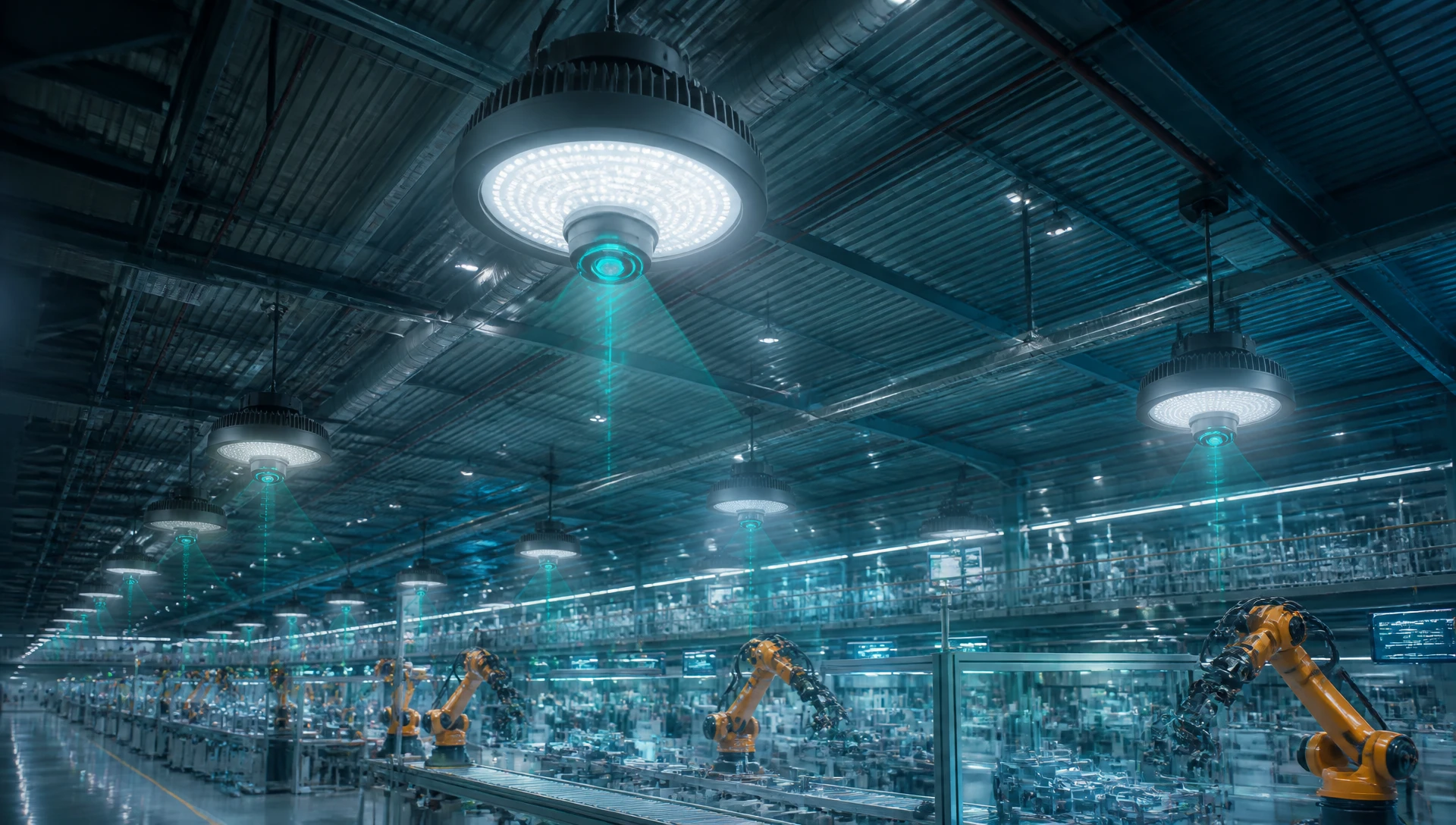
A1: Standard zone sub-metering measures the collective energy consumption of an entire branch circuit or electrical panel, which hides the performance of individual fixtures. LumiEasy’s LLLC energy reporting uses advanced data protocols to extract real-time electrical metrics directly from each individual luminaire driver, providing unparalleled granularity for diagnostic and utility tracking purposes.
A2: No. LumiEasy systems leverage highly optimized wireless mesh protocols that compress energy telemetry into tiny binary payloads. Furthermore, data transmission frequencies can be customized so that fixtures upload detailed logs during off-peak windows, ensuring your core operational networks remain unaffected.
A3: Our edge gateways process incoming OpenADR or MQTT demand-response signals from utility companies instantly. The system maps these requests to the local LLLC protocol framework, automatically adjustments power limits down to individual luminaires while continuously logging the precise drop in active power consumption to verify compliance.
Optimizing a large manufacturing facility requires high-resolution operational visibility. Transitioning from legacy lighting networks to an advanced system built on verified lllc energy reporting data collection protocols helps eliminate energy waste, secure maximum utility rebates, and provide clear data for corporate sustainability audits.
LumiEasy manufactures ruggedized, high-efficiency industrial LED lighting systems and intelligent network controls designed specifically for heavy production environments. Our hardware solutions deliver revenue-grade metering accuracy, native DALI Part 252 compliance, and secure wireless mesh connectivity tailored to the complex layouts of modern smart factories.
Don't leave valuable utility rebates and operational insights on the table. Contact our team of applications engineers and industrial automation experts today to map out an enterprise lighting topology review, configure custom data reporting setups, and secure a volume project quotation for your facility.


)
)
)
)

+86 15899791249

+86 755 2955 3313


Address: Huafeng No.1 Science and Technology Park, Sanwei, Bao'an District, Shenzhen, Guangdong, China.
