

Time:2026-08-05
In heavy industrial manufacturing, high-bay warehousing, processing plants, and expansive outdoor logistics yards, implementing centralized lighting control is a proven strategy for reducing energy consumption and operational overhead. Solid-state LED dimming platforms enable facilities to trim energy consumption dynamically based on shift schedules, task requirements, and daylight availability.
However, deploying wireless control systems across multi-acre industrial footprints presents severe radio frequency (RF) engineering challenges. Industrial facilities are hostile electromagnetic environments. Heavy electric motors, variable frequency drives (VFDs), arc welding stations, high-voltage switchgear, and dense structural steel create significant electromagnetic interference (EMI) and radio frequency interference (RFI).
When standard wireless dimmers are subjected to intense industrial noise floors, facilities experience signal packet loss, erratic dimming responses, elevated command latency, and total control node dropouts. Furthermore, solid-state phase-cut dimming circuits themselves generate rapid current switching transients (di/dt) that can radiate high-frequency noise into surrounding equipment and power lines.
Achieving reliable, long-range wireless control requires a systematic engineering approach focused on long-range rf dimmer interference mitigation. This technical guide examines the physical sources of industrial RF noise, explores the RF propagation advantages of Sub-GHz wireless architectures, details hardware and protocol-level mitigation techniques, and provides a 5-phase deployment protocol for plant engineering leads.
To design an interference-resilient wireless dimming infrastructure, facility engineers must understand how electromagnetic interference originates, propagates, and impacts wireless reception on the factory floor.
Electromagnetic interference manifests through two primary pathways in industrial environments:
Conducted EMI: Conducted interference propagates directly through electrical wiring, power distribution lines, and grounding buses. Solid-state dimmers operating on phase-cut principles (such as TRIAC leading-edge or MOSFET trailing-edge dimming) chop the AC voltage waveform 120 times per second (at 60 Hz). This rapid switching generates sharp voltage and current transients (di/dt), producing high-frequency electrical harmonics that feed back into the AC power line.
Radiated EMI: Radiated interference travels through ambient air space as electromagnetic waves. Unshielded wiring carrying high-frequency phase-cut current acts as an antenna, radiating high-frequency energy across surrounding space. Simultaneously, external industrial equipment—such as VFDs operating with fast IGBT switching frequencies—radiates broad-spectrum electromagnetic noise that corrupts incoming RF control signals at the dimmer receiver antenna.
Wireless signal integrity at the dimmer receiver node is governed by the Signal-to-Noise Ratio (SNR), which can be calculated using the following equation:
SNR (dB) = P_signal (dBm) - P_noise (dBm)
Where P_signal represents received signal power and P_noise represents ambient noise floor power.
In a clean office environment, the ambient background noise floor (P_noise) at 2.4 GHz typically ranges from -95 dBm to -105 dBm. In an active heavy manufacturing plant, unmitigated noise generated by welding equipment, induction furnaces, and VFDs can elevate the local noise floor to -70 dBm or higher.
If a transmitter outputs +10 dBm and experiences 80 dB of path loss over a 100-meter span, the received signal strength (P_signal) drops to -70 dBm. In an office, an SNR of 25 dB guarantees reliable packet decoding. In a noise-heavy industrial plant, an SNR of 0 dB causes total frame corruption, leading to unresponsive dimming zones and network instability.
Selecting the optimal radio frequency spectrum is the foundational step in mitigating long-range RF interference. While 2.4 GHz wireless technologies (such as Wi-Fi, standard Bluetooth, and Zigbee) are widespread in commercial buildings, Sub-GHz frequency bands (such as 868 MHz in Europe and 915 MHz in North America) offer fundamental physical advantages for industrial long-range wireless dimming.
The physical behavior of electromagnetic waves is inverse to their frequency. The Free-Space Path Loss (FSPL) formula illustrates why lower frequencies propagate further over long distances:
FSPL (dB) = 20 * log10(d) + 20 * log10(f) + 20 * log10(4 * pi / c)
Where d is distance, f is frequency, pi is approximately 3.14159, and c is the speed of light.
Comparing a 915 MHz Sub-GHz carrier wave to a 2.45 GHz carrier wave reveals an inherent ~8.5 dB path loss advantage for Sub-GHz signals over identical distances purely from wave physics.
Furthermore, Sub-GHz RF waves feature longer physical wavelengths (~32.7 cm at 915 MHz vs. ~12.5 cm at 2.4 GHz). Longer wavelengths exhibit superior diffraction capabilities, allowing RF energy to bend around structural steel columns, machinery enclosures, and dense storage racks rather than reflecting or scattering.
To evaluate wireless control options for factory applications, consider the following technical breakdown:
| Operational Parameter | Sub-GHz Long-Range RF (LumiEasy Standard) | 2.4 GHz BLE / Zigbee Mesh | 433 MHz Unmodulated ASK/FSK | Hardwired DALI-2 / 0-10V |
| Operating Frequency | 868 MHz / 915 MHz ISM | 2.400 - 2.4835 GHz | 433 MHz License-Free | Baseband DC Current |
| Line-of-Sight Range | Up to 1,000 m (1 km) | 50 - 100 m | 100 - 200 m | 300 m max cable run |
| Obstacle Penetration | High (Long wavelength diffraction) | Low (Reflects off metal/concrete) | High (Poor data security) | N/A (Requires physical wire) |
| Industrial Noise Immunity | Superior (FHSS + Spread Modulation) | Moderate (Shares band with Wi-Fi) | Extremely Low (Unfiltered) | Immune to RF (Vulnerable to EMI) |
| Data Rate & Security | 10 - 250 kbps (AES-128 Encryption) | 1 - 2 Mbps (AES-128) | < 10 kbps (Unencrypted) | 1.2 kbps (No encryption) |
| Control Node Capacity | Up to 1,000 nodes / gateway | 250 nodes / mesh sub-grid | Limited point-to-point | 64 addresses / DALI line |
| Installation Labor Cost | Zero control wiring | Zero control wiring | Zero control wiring | High (Conduit + pull labor) |
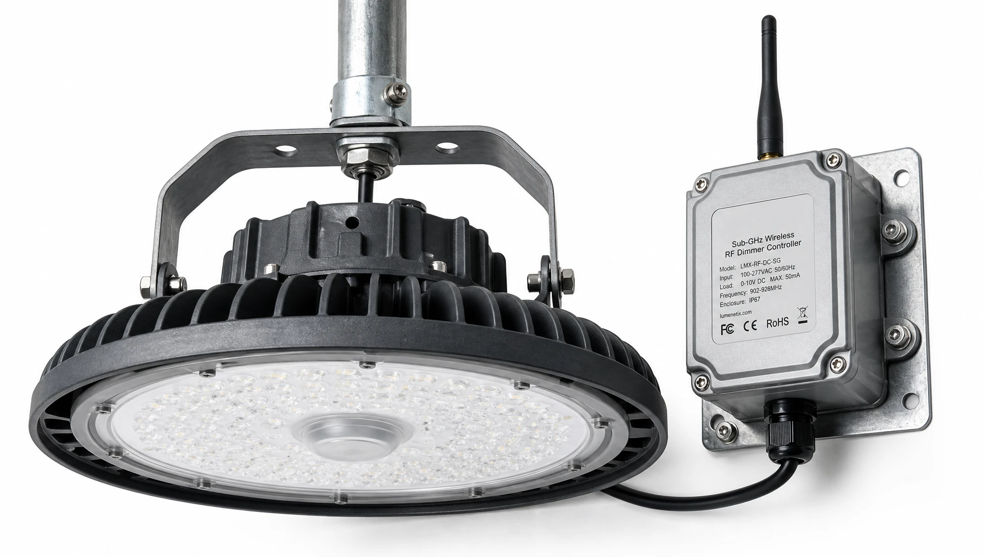
Achieving rock-solid long-range rf dimmer interference mitigation requires combining advanced wireless protocol mechanisms with hardware-level electromagnetic shielding across multiple design layers:
Static single-frequency RF channels are highly vulnerable to localized industrial interference. If a VFD or high-voltage switchgear radiates high noise at 915 MHz, a static dimmer node operating on that exact frequency will lose communication completely.
Modern industrial long-range dimming systems utilize Frequency Hopping Spread Spectrum (FHSS). The transmitter and receiver nodes hop rapidly across a pseudo-random sequence of up to 50 distinct frequency channels within the Sub-GHz band.
If a specific channel experiences heavy ambient noise or narrow-band interference, only a tiny fraction of the data burst is lost. The receiving node automatically detects the corrupted frame, requests a quick re-transmission on the next clean hop frequency, and executes the dimming command in under 50 milliseconds—making signal dropouts completely imperceptible to facility operators.
To eliminate conducted noise generated by the dimmer itself, high-performance long-range RF dimmers incorporate zero-crossing detection circuits.
By sensing the AC sine wave and triggering the internal MOSFET or IGBT switching elements precisely as the voltage passes through zero volts (0 V), the dimmer eliminates the sudden inrush of current (di/dt approaches 0). This prevents the generation of high-frequency switching harmonics.
On the line and load side, dimmers incorporate inductive-capacitive (LC) filtering networks and heavy-duty Lamp Debuzzing Coils (LDCs). These series-connected inductors slow down current rise times, filtering out residual radio frequency noise before it can enter the building power distribution lines.
Housing dimmer electronics inside grounded steel junction boxes or aluminum NEMA-rated enclosures creates a physical Faraday cage. This blocks external radiated EMI from penetrating the receiver circuit while preventing internal switching noise from radiating outward into the factory environment.
Deploying long-range wireless dimming nodes inside structural steel warehouses or heavy machinery plants requires careful network topology planning.
In high-bay logistics centers, mobile overhead cranes, elevated steel mezzanine levels, and tall stacks of metallic inventory constantly alter physical RF propagation paths. Static routing tables quickly fail under these conditions.
Industrial long-range RF dimmer platforms deploy self-healing ad-hoc mesh networking algorithms. Each dimmer node continuously measures the Received Signal Strength Indicator (RSSI) and Link Quality Indicator (LQI) of its neighboring nodes. If a moving crane or newly stacked pallet blocks the primary wireless path between two nodes, the mesh protocol automatically reroutes control packets through adjacent surrounding nodes within milliseconds, maintaining continuous link uptime across the facility.
For long-distance outdoor storage yards or multi-building industrial campuses, antenna design and placement are critical:
Fresnel Zone Clearance: The Fresnel zone is an elliptical volume surrounding the direct visual line-of-sight path between transmitter and receiver. To avoid signal reflection and phase cancellation, at least 60% of the first Fresnel zone radius (R1) must remain free of physical obstructions. The first Fresnel zone radius at its midpoint can be calculated as follows:
R1 = 8.657 * sqrt((d1 * d2) / (f * D))
Where R1 is the radius in meters, d1 and d2 are distances from the transmitter and receiver to the obstruction in kilometers, f is the frequency in GHz, and D is the total distance between transmitter and receiver in kilometers.
Elevating Sub-GHz dimmer gateway antennas above factory ceiling trusses ensures maximum Fresnel zone clearance over machinery and storage racks.
Antenna Selection: Omnidirectional 5 dBi fiberglass collinear antennas are specified for open warehouse floors, while high-gain directional Yagi or patch antennas are deployed along long narrow corridors, conveyor lines, and outdoor perimeter fencing.
To ensure seamless installation and eliminate RF interference risks, facility engineering leads should execute a structured 5-phase deployment protocol:
Phase 1: On-Site Spectrum Analysis and Ambient Noise Floor Mapping
Before procuring hardware, perform an ambient spectrum audit using an industrial spectrum analyzer. Walk the plant floor during active production hours to measure background noise levels (P_noise) across candidate frequency bands (433 MHz, 868 MHz, 915 MHz, and 2.4 GHz). Identify high-EMI noise generators such as arc welders, induction heaters, and unshielded VFD cabinets.
Phase 2: System Specification and Hardware Isolation
Specify industrial-grade long-range RF dimmers equipped with Sub-GHz radios, FHSS modulation, and zero-crossing switching hardware. Ensure all dimming modules carry robust LC line filters and are rated for wide operating temperatures (-40°C to +70°C) to withstand elevated temperatures near factory ceilings.
Phase 3: Physical Installation, Shielding, and Grounding
Install dimmer modules inside grounded metallic enclosures (such as NEMA 4X steel junction boxes) to provide physical Faraday shielding against radiated noise. Run all AC power wiring and dimmer load lines through rigid grounded steel conduit. Ensure that sensitive signal wiring is never routed in parallel conduit alongside high-voltage VFD motor leads.
Phase 4: Network Commissioning and Parameter Tuning
Using an industrial handheld commissioning tool, discover and provision dimmer nodes into logical control zones (e.g., assembly line 1, aisle 4 high-bays, shipping dock exterior). Set FHSS hopping patterns, calibrate motion sensor hold times, configure high-end trim power caps, and set packet re-transmission retries to ensure reliable frame delivery.
Phase 5: BMS Gateway Integration and Operational Stress Testing
Connect Sub-GHz wireless edge gateways to the facility's central Building Management System (BMS) or SCADA platform using BACnet/IP or MQTT protocols. Conduct a stress test by triggering full facility dimming sweeps while heavy plant equipment is operating at maximum capacity, verifying zero command packet loss and instant response times.
Deploying wireless dimming across expansive manufacturing plants, distribution hubs, and outdoor industrial yards offers compelling energy savings, operational flexibility, and lower installation costs. However, overcoming intense industrial electromagnetic interference requires moving away from fragile consumer-grade 2.4 GHz wireless devices.
By specifying Sub-GHz wireless architectures, leveraging Frequency Hopping Spread Spectrum (FHSS) protocol resilience, enforcing zero-crossing physical switching, and housing hardware in grounded metallic enclosures, plant engineering teams can achieve complete long-range rf dimmer interference mitigation.
Operating an interference-resilient wireless control infrastructure protects facilities against unpredicted downtime, extends LED driver service life, and ensures predictable, low-maintenance energy efficiency across decades of operation.
Ready to eliminate RF dropouts, resolve dimmer interference, and upgrade your industrial facility with robust Sub-GHz wireless controls? Contact our team of experienced industrial RF lighting specialists today to schedule an on-site spectrum evaluation, request custom product specifications, or receive a project quotation. Visit the official
A1: Interference originates from two sources: conducted noise caused by rapid solid-state phase-cut switching transients (di/dt) feeding back into power lines, and radiated noise emitted by heavy industrial equipment such as variable frequency drives (VFDs), electric arc welders, high-voltage transformers, and unshielded power cables.
A2: Sub-GHz frequencies (868/915 MHz) feature longer physical wavelengths that bend and diffracted around structural steel beams, metal storage racks, and heavy machinery. Sub-GHz signals suffer significantly lower free-space path loss, provide up to 10 times the operating range of 2.4 GHz systems, and completely avoid crowded 2.4 GHz corporate Wi-Fi frequency bands.
A3: LumiEasy long-range RF dimmers combine Sub-GHz Frequency Hopping Spread Spectrum (FHSS) protocols with zero-crossing switching hardware, internal LC line filters, and self-healing mesh networking. This multi-layered architecture automatically dodges active radio interference, eliminates conducted power line noise, and guarantees reliable dimming control across extreme industrial environments.


)
)
)
)

+86 15899791249

+86 755 2955 3313


Address: Huafeng No.1 Science and Technology Park, Sanwei, Bao'an District, Shenzhen, Guangdong, China.
