Time:2026-08-21
In heavy manufacturing facilities, chemical processing plants, automotive assembly halls, and high-density logistics hubs, emergency egress illumination is a non-negotiable safety requirement. When main AC power fails during an industrial blackout, grid disturbance, or local electrical trip, life safety codes dictate that emergency luminaires must immediately illuminate escape routes, hazardous machinery zones, and exit pathways.
However, managing hundreds or thousands of individual emergency light fittings across sprawling industrial campuses presents a severe operational challenge. Traditional manual maintenance—where facility technicians walk every aisle with physical ladders, manually trigger test switches, and log battery runtimes on paper ledgers—is inherently labor-intensive, error-prone, and economically inefficient.
Adopting centralized emergency lighting monitoring transforms life safety infrastructure from a passive operational liability into an automated, digitally verified asset. By integrating intelligent DALI-2 emergency drivers, addressable central gateways, and automated testing software, industrial facility managers can guarantee continuous code compliance, lower maintenance overhead, and eliminate dangerous lighting blind spots across their facilities.
Centralized emergency lighting monitoring is an integrated digital network architecture designed to continuously track, test, and report the operational status of every emergency fixture across a facility from a single user interface or Building Management System (BMS).
Unlike traditional standalone emergency lights—which rely on local battery packs and visual green/red LED indicators requiring physical inspection—a centralized monitoring network establishes two-way digital communication between individual emergency LED drivers and a central management panel or cloud server.
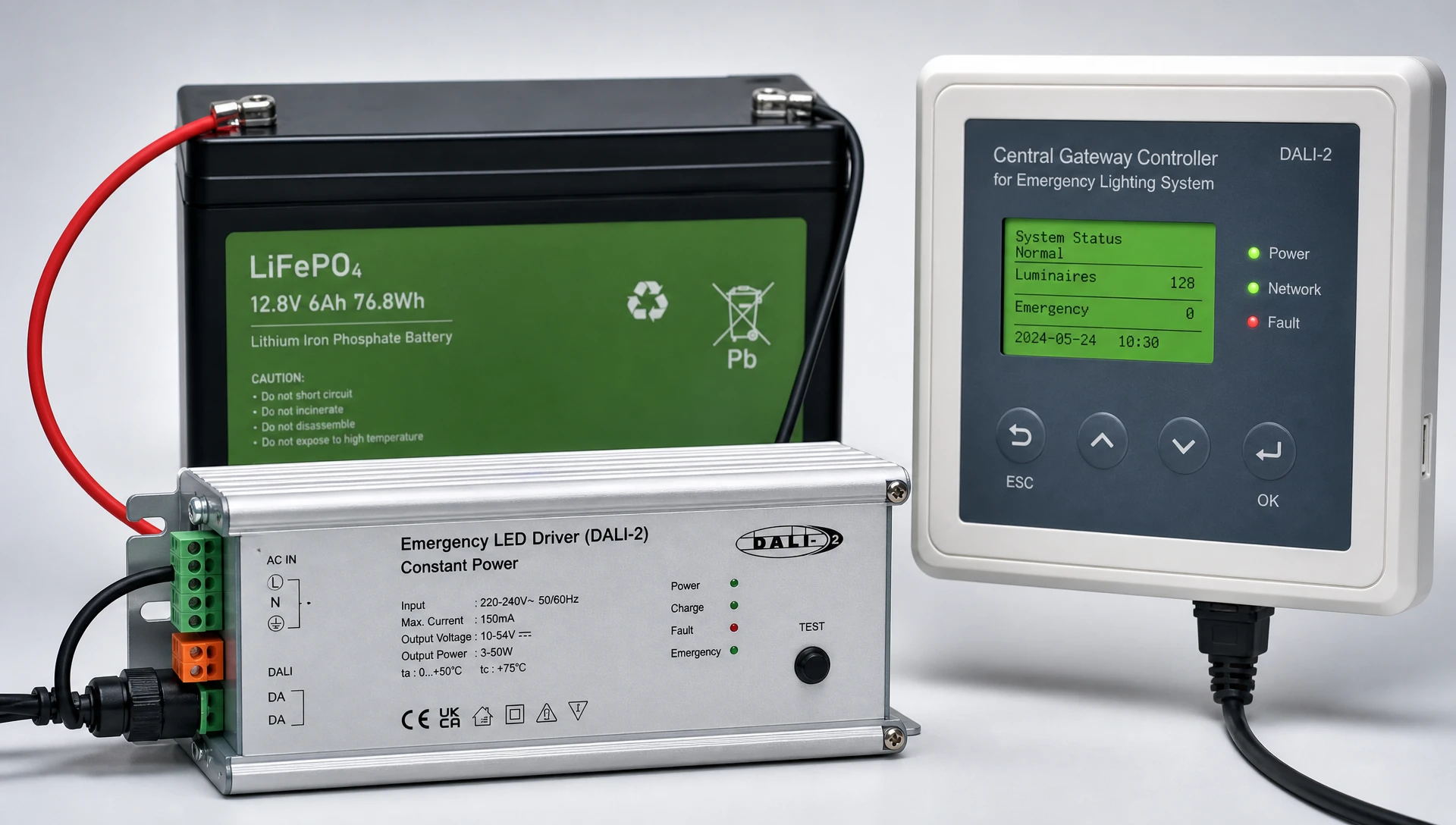
Addressable Emergency LED Drivers: Intelligently managed emergency power supplies installed inside or adjacent to industrial luminaires. These drivers integrate local battery charging circuits, mains failure sensing logic, and digital communication transceivers.
Central Monitoring Panel / Gateway: A specialized hardware controller that polls individual emergency nodes, executes scheduled automated testing routines, and aggregates system diagnostic logs.
Emergency Battery Architecture: Depending on plant layout, emergency power is supplied either via localized internal batteries (Decentralized Individual Battery Systems) or a high-capacity rack-mounted Central Battery System (CBS).
Communication Bus: The physical or wireless media conveying control commands and diagnostic telemetry between the gateway and emergency luminaires.
The backbone of modern centralized emergency monitoring relies on open, standardized digital protocols:
DALI-2 Emergency Standard (IEC 62386-202): Defines the standard specifications for self-contained emergency lighting control gear (Device Type 1). DALI-2 provides bidirectional digital monitoring over a polarity-independent, two-wire bus line, returning precise error codes such as battery failure, lamp failure, or charging circuit degradation.
Wireless Mesh Protocols (Zigbee / Bluetooth NLC): Ideal for retrofitting existing manufacturing plants where pulling new two-wire control cables through conduit is cost-prohibitive. Each luminaire acts as a repeater node, forming a robust, self-healing network that routes emergency diagnostic data around industrial obstructions.
Pro-Tip for Plant Engineers: When deploying wired DALI-2 control loops across dusty manufacturing bays, maintain a maximum bus line length of 300 meters using 1.5 mm² (AWG 16) cross-section copper wire. Ensure line voltage drop across the DALI bus never exceeds 2.0 V to prevent bus power starvation at distant emergency nodes.
Industrial facility owners face strict legal obligations regarding emergency egress illumination. Regulatory frameworks across major industrial markets—including NFPA 101 (Life Safety Code) in North America, EN 50172 / BS 5266 in Europe, and GB 17945 in China—mandate two primary operational verification tests:
Functional Test (Short-Term): Executed monthly. The system disconnects AC mains power to emergency fixtures for 30 to 60 seconds to verify that the emergency driver switches to battery power, the inverter strikes the LED light engine, and the lamp operates correctly.
Duration Test (Full-Term): Executed annually (or semi-annually). The system cuts mains power for the full statutory emergency runtime—typically 1 to 3 hours (180 minutes). This verifies that the emergency battery maintains required lux levels across the entire egress corridor until the rating period ends.
Centralized emergency monitoring automates these mandatory routines without requiring manual intervention. Intelligently managed drivers continuously monitor battery internal impedance, charging current, and terminal voltage curves during discharge phases.
The system calculates real-time battery degradation by evaluating actual measured discharge capacity against the manufacturer's nominal rating:
Formula: SoH (%) = (Actual Measured Discharge Capacity in Ah / Rated Nominal Capacity in Ah) * 100
If the calculated SoH falls below 80% during an automated annual Duration Test, the central monitoring panel instantly flags a maintenance alarm, alerting technicians to replace the battery pack before a catastrophic failure occurs during a real emergency.
To determine the total energy stored required for high-bay emergency fixtures operating under extreme thermal conditions, plant engineers apply the following capacity equation:
Formula: Total Energy (Wh) = (Emergency Driver Output Power in Watts * Required Backup Duration in Hours) / Inverter Conversion Efficiency
Where Inverter Conversion Efficiency typically ranges between 0.85 and 0.92 depending on thermal management and driver topography.
To explore high-efficiency emergency control equipment built to these exact specifications, review the technical parameters of specialized
+--------------------------------------------------------------------------------------------------+
|                              AUTOMATED TESTING TIMELINE & LOGGING                                |
|                                                                                                  |
|   Day 01 (Monthly) ----> Automated 30-Sec Functional Test (FT) ----> Log Status to BMS           |
|   Day 30 (Monthly) ----> Automated 30-Sec Functional Test (FT) ----> Log Status to BMS           |
|   ...                                                                                            |
|   Day 365 (Annual) ----> Automated 180-Min Duration Test (DT)  ----> Generate Compliance PDF     |
+--------------------------------------------------------------------------------------------------+
Selecting the right system architecture is a crucial preliminary decision for plant design engineers. Both Central Battery Systems (CBS) and Decentralized Individual Battery Systems (DIBS) can be fully monitored from a centralized head-end interface, but their physical footprints and installation profiles differ significantly.
| Engineering Metric | Central Battery System (CBS) | Decentralized Individual Battery System (DIBS) |
| Battery Location | Single rack-mounted cabinet in dedicated plant room | Self-contained inside or adjacent to each fixture |
| Wiring Infrastructure | Fire-resistant cable (E30/E90 rated) to every light | Standard industrial mains wiring + DALI-2 control bus |
| Thermal Protection | Excellent (Battery room is climate-controlled) | Requires high-temp batteries (e.g., LiFePO4 up to 60°C) |
| System Single Point of Failure | High (Central inverter/rack failure affects zone) | Very Low (Failure isolated to single fixture node) |
| Initial Capital Expenditure (CapEx) | High (Expensive fire-rated cabling & central rack) | Moderate (Standard luminaire wiring) |
| Long-Term Operational Maintenance | Simple (Replace batteries in one central room) | Distributed (Technicians replace batteries at fixture) |
| Central Monitoring Method | Sub-station monitoring via Modbus / BACnet | Addressable DALI-2 / D4i network per fixture |
In chemical processing bays, flour mills, or food manufacturing halls requiring IP65/IP67 washdown protection or ATEX / IECEx hazardous location ratings, self-contained individual battery systems with centralized DALI-2 monitoring offer superior modularity.
Because each emergency luminaire carries its own internal LiFePO4 battery, a damage event in one high-vibration zone does not disrupt emergency lighting across adjacent plant bays.
For deep insight into industrial safety compliance and software integration strategies, consult this detailed guide on how
Proper physical deployment and electrical isolation are essential to prevent data corruption across industrial communications networks.
DALI-2 control loops allow flexible star, daisy-chain, or tree topologies, but circular loop configurations must be strictly avoided to prevent packet collision.
Voltage Range: The DALI bus operates at a nominal 16 V DC (guaranteed range 12 V to 22.5 V DC).
Bus Power Supplies: Industrial gateways must include integrated or external DALI bus power supplies limited to a maximum current of 250 mA per channel.
Grounding & Immunity: Although DALI signals tolerate high electrical noise levels, routing DALI bus cables parallel to high-voltage variable frequency drive (VFD) output cables for distances exceeding 10 meters can induce high-frequency noise. Maintain a minimum physical clearance of 300 mm between control cables and 400 V power lines.
During commissioning, the centralized controller executes an automated short-address assignment procedure, giving every emergency driver a unique digital identifier between 0 and 63 per DALI channel.
Emergency luminaires are then assigned to functional logical groups:
Group 1: Main Processing Floor High-Bay Egress
Group 2: Emergency Exit Stairwell Luminaires
Group 3: Hazardous Chemical Storage Area Lighting
This logical grouping allows maintenance managers to stagger annual Duration Tests. Testing 100% of emergency fixtures simultaneously leaves the factory temporarily vulnerable if an actual blackout occurs immediately after a full discharge test, while batteries are still recharging. Staggering duration tests across alternate groups ensures 50% battery reserve capacity is always maintained across every zone.
To review step-by-step physical installation diagrams and signal routing principles, read the technical guide on
Designing a compliant emergency lighting architecture for high-bay industrial plants or hazardous environments? Download LumiEasy’s Emergency Lighting Network Layout & Gateway Wiring Guide (PDF) or speak directly with our Senior Lighting Application Engineers for a free DALI loop voltage drop calculation.
Transitioning from manual inspections to automated centralized emergency lighting monitoring provides a rapid financial return on investment (ROI).
Facility Profile:
Plant Type: Heavy Equipment Manufacturing Facility (40,000 m² / 430,000 sq.ft)
Total Emergency Luminaire Count: 1,000 Addressable Emergency Fixtures
Fully Loaded Technician Labor Rate: $60 / hour
Regulatory Requirement: 12 Monthly Functional Tests + 1 Annual 3-Hour Duration Test per year
| Cost Vector | Traditional Manual Testing & Paper Logging | Centralized Automated Monitoring System |
| Annual Functional Testing Labor | $36,000 (1,000 hrs/yr @ $60/hr) | $0 (100% Automated Digital Self-Test) |
| Annual Duration Testing Labor | $24,000 (400 hrs/yr @ $60/hr) | $0 (100% Automated Scheduled Test) |
| Manual Data Entry & Audit Log Prep | $7,200 (120 hrs/yr @ $60/hr) | $300 (Automated One-Click PDF Report) |
| Production Downtime / Scaffolding Costs | $15,000 / year | $1,500 / year (Targeted Maintenance Only) |
| Unplanned Emergency Battery Failures | High (Undetected between manual checks) | Near Zero (Predictive SoH Telemetry) |
| Total Annual Operational Overhead | $82,200 / year | $1,800 / year |
Annual Operational Savings: $80,400 per year
10-Year Cumulative OpEx Reduction: $804,000
Estimated Hardware & Gateway Initial Premium: $35,000
Simple Hardware Payback Period: 5.2 Months
In addition to direct labor savings, automated systems generate time-stamped digital compliance records that satisfy fire marshals, local code enforcement inspectors, and corporate insurance auditors, eliminating the risk of costly regulatory fines or facility shutdown orders.
To explore the control infrastructure that enables these operational savings, examine the modular design of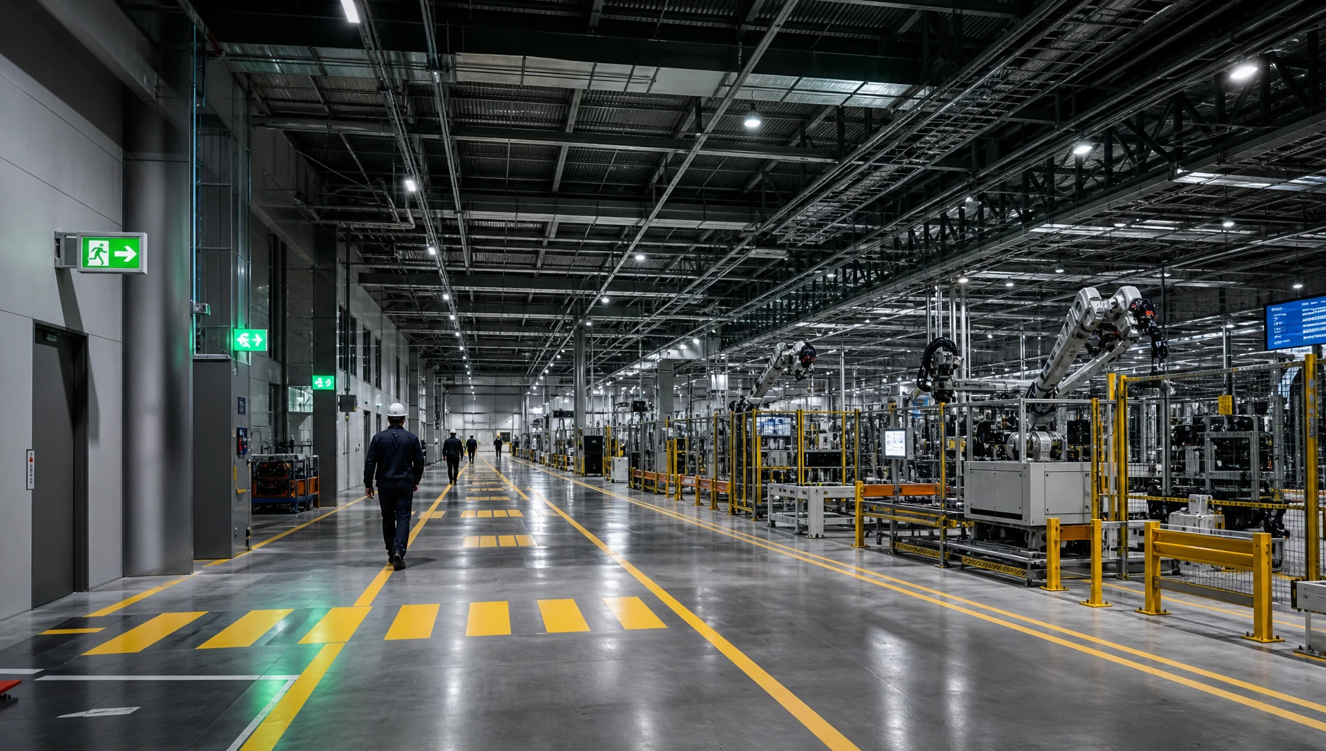
In noisy industrial electrical environments, field technicians occasionally encounter communication or battery diagnostics anomalies. Use the following framework for rapid root-cause isolation:
Root Cause A: Excessive signal attenuation due to long cable runs or undersized wire gauge causing bus voltage to drop below 10.5 V DC at distant fixtures.
Remedy: Measure DC voltage across the DALI terminals at the furthest luminaire. If voltage is below 12 V DC, split the line using a DALI repeater or install an auxiliary bus power supply.
Root Cause B: Ground loops created by accidental contact between the unpolarized DALI bus lines and grounded steel cable trays.
Remedy: Perform an insulation resistance test (Megger test at 500 V DC) between the DALI wires and structural ground while the line is powered off. Ensure insulation resistance exceeds 1 Megohm.
Root Cause: Operating ambient temperatures exceeding battery ratings (e.g., standard NiCd/NiMH batteries exposed to 50°C temperatures near radiant industrial ovens).
Remedy: Replace standard emergency battery packs with high-temperature Lithium Iron Phosphate (LiFePO4) battery packs rated for continuous 60°C operation, or relocate battery enclosures away from heat sources.
Root Cause: Replacement emergency drivers installed during routine maintenance without clearing their factory default short addresses.
Remedy: Run a re-addressing command from the LumiEasy central gateway console to automatically detect and resolve address collisions across affected DALI loops.
Using standard 1.5 mm² copper cable, a single DALI-2 control bus supports a maximum wire length of 300 meters from the central gateway to the furthest emergency driver. For larger industrial campuses, multiple gateways can be networked over an IP backbone (Ethernet / Fiber / Wi-Fi) to monitor tens of thousands of emergency fixtures across unlimited distances.
Life safety codes like EN 50172 and NFPA 101 mandate a full-duration test (typically 1 to 3 hours) once every 12 months, along with short monthly functional tests. LumiEasy centralized monitoring controllers allow plant operators to automate these schedules during off-peak hours and stagger tests across alternate fixture groups to preserve backup capacity.
Yes. LumiEasy central gateways support standard open industrial protocols including BACnet/IP, Modbus TCP/RTU, and RESTful APIs. This enables real-time emergency lighting fault alarms, battery state-of-health data, and automated test reports to feed directly into centralized Building Management Systems or enterprise asset management dashboards.
Implementing centralized emergency lighting monitoring is an essential strategy for modernizing industrial facility management. By replacing manual inspection routines with automated DALI-2 testing and continuous digital diagnostic tracking, plant operators can ensure absolute compliance with global life safety codes, protect personnel, and substantially reduce ongoing operational maintenance costs.
To analyze your facility’s emergency egress infrastructure, request custom DALI loop engineering drawings, or consult with our life safety technical specialists,


)
)
)
)

+86 15899791249

+86 755 2955 3313


Address: Huafeng No.1 Science and Technology Park, Sanwei, Bao'an District, Shenzhen, Guangdong, China.