

Time:2026-08-25
Industrial manufacturing environments—ranging from heavy automotive fabrication halls and chemical processing bays to high-density logistics fulfillment hubs—are undergoing a continuous digital transformation. Historically treated merely as a necessary operational utility, industrial lighting infrastructure is rapidly evolving into an intelligent, data-gathering backbone for the Industrial Internet of Things (IIoT).
At the epicenter of this technological shift is the deployment of dali d4i certified luminaires. Standardized by the Digital Illumination Interface Alliance (DiiA) and governed by strict International Electrotechnical Commission (IEC) specifications, D4i represents the advanced extension of the established DALI-2 protocol.
By integrating standardized memory banks, intra-luminaire bus power supplies, and universal sensor sockets directly into the fixture, D4i-certified high bays, low bays, and linear vapor-tight luminaires allow plant managers to capture granular energy consumption metrics, monitor driver thermal health, and automate predictive maintenance across thousands of industrial lighting nodes.
To understand why dali d4i certified luminaires are becoming mandatory in enterprise industrial procurement specs, facility engineers must examine the technical framework established by the DiiA under IEC 62386.
While traditional DALI-2 focuses primarily on standardizing bi-directional control communication between external gateways, sensors, and LED control gear, D4i specifically standardizes the luminaire as an intelligent node capable of storing, processing, and reporting critical operational data.
Every luminaire achieving genuine D4i certification must incorporate LED control gear (drivers) that strictly comply with four key parts of the IEC 62386 standard:
Integrated Bus Power Supply (IEC 62386 Part 250): In standard DALI networks, an external bus power supply unit (PSU) is required to energize the two-wire control bus. D4i drivers integrate a regulated, switchable DALI bus power supply directly inside the driver electronics. This integrated supply delivers up to 52 mA (typically guaranteed at 50 mA) of current directly onto the internal DALI bus, eliminating the need for external power supplies to energize attached sensor nodes or wireless mesh transceivers.
Luminaire Asset Data (IEC 62386 Part 251 / Memory Bank 1): Part 251 standardizes the encoding of luminaire physical parameters within a read-only memory location known as Memory Bank 1. During manufacturing, the fixture vendor writes unique identification parameters directly into the driver, including the Global Trade Item Number (GTIN), nominal light output, CCT/CRI parameters, electrical wattage, and optical distribution geometry.
Energy & Power Reporting Data (IEC 62386 Part 252 / Memory Bank 2): Part 252 introduces real-time power metering capabilities directly into the LED driver circuitry. Standardized memory structures in Bank 2 continuously log active power consumption (Watts), total active energy (kWh), apparent power (VA), power factor, and AC input voltage/current.
Diagnostics & Maintenance Telemetry (IEC 62386 Part 253 / Memory Bank 3): Part 253 provides operational diagnostics designed for proactive facility management. It continuously tracks control gear operating hours, logs internal driver temperatures, records maximum historical thermal spikes, and flags LED light engine failure events.
For a deeper technical evaluation of certified driver topology, explore our detailed technical guide on
Pro-Tip for Plant Engineers: When reviewing supplier compliance datasheets, ensure the control gear carries official DiiA certification seals rather than unverified "D4i compliant" text claims. Genuine D4i certification requires rigorous testing through accredited DiiA test houses to guarantee inter-operability between different sensor brands and central gateways.
The mechanical and electrical interface between the luminaire housing and external control nodes is crucial for scalable industrial IoT deployments. D4i works in tandem with standardized connector ecosystems—specifically Zhaga Book 18 and ANSI C136.41 (NEMA 7-pin)—to create a modular, future-proof hardware environment.
Zhaga Book 18 specifies a compact, 4-pin receptacle designed specifically for IP65/IP67 outdoor and industrial indoor LED luminaires. Combined with a D4i driver, the socket pinout provides:
Pin 1: +24 V DC auxiliary power supply (derived from an integrated AUX power supply per IEC 62386-150, providing up to 3 W continuous power for high-demand wireless mesh radios).
Pin 2: DALI- / GND connection.
Pin 3: DALI+ signal line (carrying 16 V DC DALI control signaling and Part 250 bus power).
Pin 4: General purpose IO / logical control signal.
For complex manufacturing bays requiring both multi-technology occupancy sensing and long-range wireless mesh connectivity, D4i architecture supports dual Zhaga sockets on a single fixture:
Bottom Socket (Zhaga Book 18): Houses a high-bay microwave or Passive Infrared (PIR) motion sensor operating at high mounting heights (12–18 meters).
Top Socket (Zhaga Book 18): Houses a Bluetooth Networked Lighting Control (NLC) or Zigbee 3.0 mesh transceiver node that communicates fixture telemetry to the enterprise server.
Because the D4i driver acts as a central power distributor and data hub over the internal DALI bus, both nodes operate seamlessly without requiring separate external power adapters or supplementary wiring harnesses.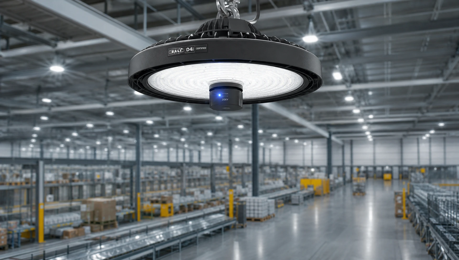
Modern manufacturing plants operate on strict schedules where unplanned equipment downtime leads to significant financial loss. Implementing dali d4i certified luminaires shifts lighting maintenance from a reactive model to a fully automated predictive framework.
In traditional industrial installations, mapping thousands of high-bay fixtures to physical plant floor layouts requires manually cataloging serial numbers, fixture wattages, and beam patterns on paper logs during installation.
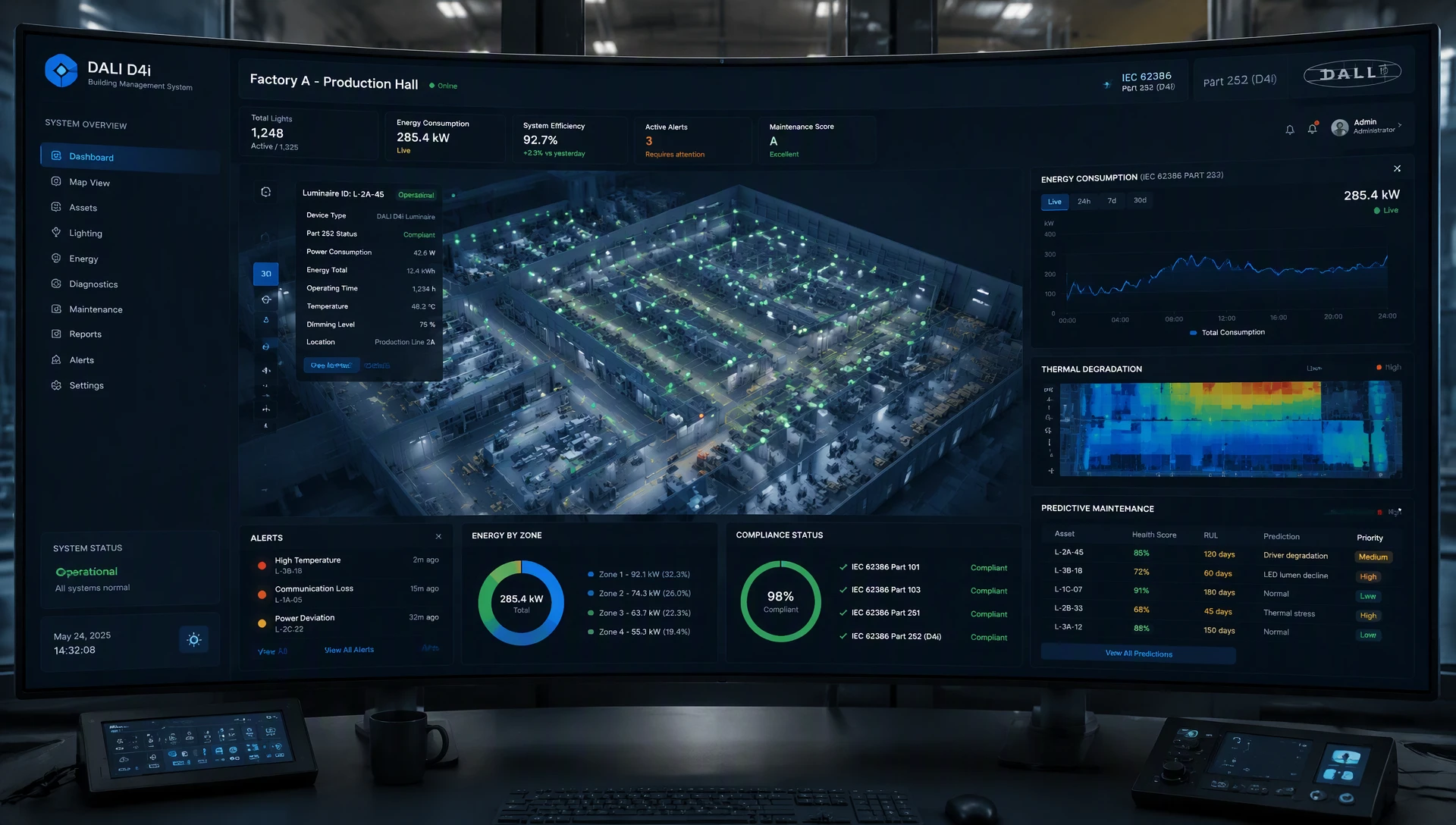
With D4i-certified luminaires, as soon as AC power is applied, the wireless mesh node reads the stored asset data from Memory Bank 1 (IEC 62386-251) via the internal DALI bus. The node transmits the GTIN, model number, rated power, optical characteristics, and initial manufacturing date to the central management dashboard, allowing the building management system (BMS) to automatically populate its digital twin model and reduce commissioning labor by up to 80%.
Electrolytic capacitors inside LED drivers are highly sensitive to elevated thermal stress. Operating an LED driver continuously at elevated temperatures significantly reduces its operational lifespan:
45°C to 75°C (Standard Operating Range): The driver operates at peak efficiency, maintaining its maximum rated lifespan of 120,000 hours (with 65°C serving as the standard operating baseline).
75°C to 85°C (Elevated Thermal Stress): Thermal degradation accelerates rapidly, causing expected driver lifespan to drop to 40,000 hours.
Above 85°C (Critical Thermal Degradation): Electrolytic fluid evaporation causes catastrophic component failure, reducing operational lifespan down to 20,000 hours or less.
Through IEC 62386 Part 253 telemetry, plant engineers receive automated alerts whenever a luminaire's internal driver temperature exceeds safe operating thresholds, allowing technicians to rectify thermal hazards long before driver failure occurs.
Planning a high-bay lighting upgrade or building an ISO 50001 compliant industrial plant? Download LumiEasy’s D4i Driver System Engineering & Sensor Wiring Guide (PDF) or request a free technical consultation with our Senior Lighting Application Engineers.
Deploying D4i networks in high-noise electrical environments—such as plants operating heavy variable frequency drives (VFDs), electric arc furnaces, or high-power resistance welders—requires strict adherence to signal isolation and wiring parameters.
Step 1: Physical Bus Topology & Isolation Verification
Verify that the total bus cable length is $\le 300\text{ meters}$ using $1.5\text{ mm}^2$ copper wire. Ensure a minimum physical clearance of $300\text{ mm}$ from $400\text{ V}$ motor feeder lines to prevent signal degradation.
Step 2: Bus Power Supply Current Budgeting
Audit internal D4i driver Part 250 power supplies across all nodes. Ensure the combined bus power across all active drivers does not exceed the $250\text{ mA}$ safety limit.
Step 3: Automated Node Discovery & Short Address Allocation
Execute the DALI search algorithm via the central gateway panel. Automatically discover connected devices and assign unique short addresses (ranging from 0 to 63 per DALI channel).
Step 4: Memory Bank Telemetry Parsing & GIS Mapping
Query Memory Bank 1 (IEC 62386-251) to extract the fixture's GTIN, rated wattage, and nominal lumen output. Map luminaires directly onto digital floor plans within the BMS interface.
Step 5: Automated Testing Schedule & Energy Threshold Setup
Configure automated energy polling frequencies according to IEC 62386-252. Establish thermal warning and operational failure diagnostic thresholds under IEC 62386-253.
To ensure trouble-free physical deployment, review our detailed guide on the
A critical distinction in D4i installations is managing the integrated bus power supply (Part 250). When multiple D4i drivers are wired together on a shared internal DALI line, enabling the Part 250 power supply on every driver simultaneously could cause total line current to exceed the mandatory 250 mA safety limit specified by DALI standards.
Bus Power Budget Formula: Total Bus Current (I_total) = Sum of I_supply for all active drivers (k = 1 to N) <= 250 mA
Calculation Warning Example: 10 drivers * 50 mA = 500 mA (Exceeds the 250 mA Maximum limit)
Pro-Tip for Plant Engineers: In multi-driver luminaires (such as high-output 600W industrial high bays utilizing two or three 200W D4i drivers), enable the Part 250 bus power supply on only one driver. Deactivate the Part 250 software bit on the remaining slave drivers via software commissioning to maintain a safe 50 mA bus supply for attached sensors.
Industrial facility operators facing strict corporate ESG targets or undergoing ISO 50001 Energy Management Systems accreditation require precise energy data validation. Traditional estimation methods—multiplying nominal lamp wattage by operating hours—fail to account for line voltage fluctuations, thermal driver efficiency drift, or dimming curve non-linearities.
D4i drivers undergo rigorous testing to guarantee high-precision power measurement across their dimming range:
Measurement Error Formula: Measurement Error (%) = [(Measured Power - Actual Power) / Actual Power] * 100 <= +-1.0%
When operating between 50% and 100% load, D4i drivers deliver Class 1 accuracy (≤± 1.0% error margin). Even when dimmed down to 10% output, accuracy remains within ± 5.0%, providing verifiable data suitable for utility rebate calculations and corporate carbon audits.
For comprehensive strategies on utilizing fixture telemetry to optimize plant performance, read our analysis on
Plant Operating Parameters:
Fixture Count: 500 High-Bay Luminaires (200W nominal per fixture)
Annual Operating Hours: 6,000 hours/year (24/7 manufacturing floor)
Electricity Cost: $0.14 / kWh
Facility Floor Area: 25,000 m²
| Financial & Operational Metric | Legacy 0-10V Dimming | Standard DALI-2 (No D4i) | DALI D4i Certified Luminaires |
| Control Signal Architecture | Analog 2-Wire (Unidirectional) | Digital 2-Wire (Bi-directional) | Digital D4i + Zhaga IoT Nodes |
| Luminaire Data & Asset Mapping | Manual Paper Records | Manual Database Entry | Automated (IEC 62386-251) |
| Energy Consumption Tracking | External Metering Estimated | External Zone Metering | Real-Time Class 1 (IEC 62386-252) |
| Diagnostic Maintenance Telemetry | None (Visual Inspection Only) | Basic Driver Failure | Predictive Thermal & SoH (Part 253) |
| Annual Energy Cost | $84,000 | $50,400 | $37,800 (Dynamic Occupancy & Data) |
| Annual Maintenance Labor Cost | $18,500 | $11,200 | $2,400 (Predictive Targeted Maintenance) |
| 10-Year Total Operating Expense | $1,025,000 | $616,000 | $402,000 |
| 10-Year Net Savings vs. 0-10V | Baseline | $409,000 | $623,000 |
The financial data confirms that while dali d4i certified luminaires carry a modest initial procurement premium, the combined energy savings and operational labor reductions yield a full payback within 14 months of installation.
When deploying high-density D4i networks across complex manufacturing plants, maintenance personnel can resolve common field errors using systematic diagnostic routines:
Symptom: Wireless Zhaga mesh nodes fail to boot up or frequently drop off the mesh network.
Root Cause: The integrated Part 250 bus power supply inside the driver has been disabled during commissioning, or total cable impedance exceeds limits.
Remedy: Connect a digital multimeter across DALI+ and DALI- at the socket. If reading is below 12 V DC, access the driver parameters via your commissioning tool and toggle the Part 250 enable bit to ON. Verify that DC voltage rises to a nominal 16 V DC.
Symptom: Central gateway reports invalid GTIN or corrupted energy consumption logs from Memory Bank 2.
Root Cause: High-voltage transient noise induced onto unshielded control cables running parallel to unshielded motor leads from heavy VFD equipment.
Remedy: Ensure DALI control cables cross high-voltage motor feeds at a 90-degree angle rather than running parallel. Confirm that the luminaire housing earth grounding bond meets IEC 60598-1 standards to shunt high-frequency common-mode noise away from the driver electronics.
DALI-2 standardizes basic control commands and inter-operability for control gear, sensors, and switches. D4i builds directly upon DALI-2 by mandating integrated DALI bus power (Part 250) and requiring standardized memory banks inside the driver for luminaire asset tracking (Part 251), real-time energy reporting (Part 252), and advanced driver diagnostics (Part 253).
Yes. One of the core engineering benefits of D4i certification is full vendor-independent inter-operability. Any DiiA-certified Zhaga Book 18 or NEMA control node (utilizing Bluetooth NLC, Zigbee, or cellular protocols) can draw power directly from a LumiEasy D4i driver and read its internal memory telemetry over the DALI bus.
LumiEasy D4i-certified LED drivers are engineered with high-temperature solid-state capacitors and ruggedized aluminum housings. They incorporate automated thermal fold-back mechanisms that monitor internal temperatures via IEC 62386 Part 253, protecting the driver against permanent thermal damage even in continuous 60°C ambient plant conditions.
Transitioning to dali d4i certified luminaires provides industrial manufacturing facilities with a standardized, data-rich lighting infrastructure engineered for the future of digital plant operations. By capturing precise energy metrics, enabling predictive maintenance, and streamlining IoT node integration, D4i technology transforms industrial illumination into an invaluable operational asset.
To review technical drawings, evaluate custom driver configurations, or discuss high-bay lighting specifications for your next facility expansion,


)
)
)
)

+86 15899791249

+86 755 2955 3313


Address: Huafeng No.1 Science and Technology Park, Sanwei, Bao'an District, Shenzhen, Guangdong, China.
