

Time:2026-07-24
A DALI D4i sensor ready interface gives a luminaire a defined place for a sensor, photocell, wireless node or other luminaire-mounted control device. The interface can simplify installation and future upgrades, but the label alone does not confirm that two products will work together.
For a commercial lighting project, the team must verify four separate layers:
Electrical compatibility: The D4i driver supplies the required bus power and, where needed, auxiliary power.
Communication compatibility: The driver and control device implement the relevant DALI requirements.
Mechanical compatibility: The plug, receptacle, mounting position and environmental protection match.
Control and data compatibility: The sensor produces the required occupancy, daylight, energy or diagnostic data, and the gateway or management platform can use it.
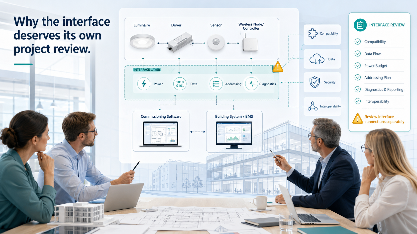
The DALI Alliance describes D4i as an extension of DALI-2 for intelligent, IoT-ready luminaires. D4i drivers support standardized luminaire, energy and diagnostics data, while D4i control devices use Part 351 requirements. This creates a stronger technical foundation than a luminaire that simply has an unused socket. D4i overview, DALI Alliance
For a basic explanation of the technology, read LumiEasy's DALI D4i sensor ready interfaces overview. This commissioning guide focuses on the specification, verification and acceptance decisions that determine whether a sensor-ready design performs as intended.
DALI D4i sensor ready interfaces are electrical, communication and mechanical provisions that allow a luminaire to accept a compatible D4i sensor or control device. A typical arrangement includes a D4i LED driver, a powered receptacle, a luminaire-mounted control device and, when required, a wireless network lighting controller or gateway.
D4i handles the digital control, power and data requirements inside the luminaire. A Zhaga-D4i design adds a standardized mechanical interface, such as a Zhaga receptacle, to support a compatible sensor or communication module. The two terms describe related but different parts of the design.
The interface can support:
Occupancy or movement sensing
Daylight measurement and daylight harvesting
Luminaire-level dimming
Wireless network lighting control
Energy reporting
Luminaire diagnostics and asset information
Local control without a gateway, when the selected device supports the required logic
Wider building or cloud connectivity through a network node or gateway
The practical value appears during the next project phase. A facility team can replace a failed node, add wireless connectivity or change the sensing strategy without redesigning the entire luminaire. That outcome depends on the certification, pinout, device type, firmware and commissioning method specified at the start.
These terms often appear together in specifications, but they do not mean the same thing.
| Term | What it defines | What the project team should verify |
DALI | Digital addressable lighting control protocol | Device functions, wiring and system architecture |
DALI-2 | Certification program and expanded requirements built on IEC 62386 | Certified driver and control-device status |
D4i | DALI-2 extension for intelligent luminaires, including power and standardized data requirements | Parts 250 to 253 for drivers and Part 351 for luminaire-mounted control devices |
Zhaga-D4i | Joint Zhaga and DALI Alliance approach combining a Zhaga mechanical interface with D4i requirements | Certified luminaire and certified node or sensor, plus the correct Book 18 or Book 20 architecture |
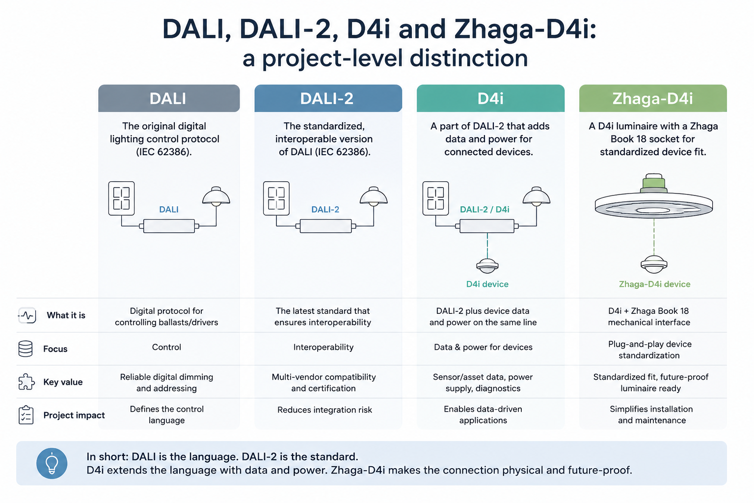
The DALI Alliance states that D4i certification extends DALI-2 certification, so a D4i device is also a DALI-2 device. The Alliance product database lists certified components and records the specific product identity, hardware and firmware versions covered by certification. DALI Alliance Product Database
Do not write “D4i compatible” as the only requirement in a tender. Ask for the relevant certification or documented compliance, the exact model number and the interface configuration. A similar-looking socket can have a different pin assignment, power provision or control-device class.
The driver sits at the center of the luminaire-level DALI bus. For D4i driver certification, the DALI Alliance identifies Part 250 for integrated bus power and Parts 251, 252 and 253 for luminaire, energy and diagnostics data. Part 150, which covers an auxiliary 24 V supply, is optional in the driver certification requirements but becomes important when the control device needs more power than the DALI bus can provide.
Record the driver brand, model, firmware version, D4i status and available auxiliary supply in the submittal. A driver described as “DALI dimmable” does not automatically provide the complete D4i feature set.
The receptacle determines how the control device attaches to the luminaire. Check the number of terminals, the orientation, the sealing method, the mounting surface, the allowable rotation and the protection rating required by the installation environment.
For outdoor projects, Zhaga Book 18 covers the smart interface between outdoor luminaires and sensing or communication modules. Zhaga Book 20 applies to indoor luminaire-mounted control devices. Do not treat a Book 18 design and a Book 20 design as interchangeable simply because both use the Zhaga name.
DALI Part 351 defines four D4i luminaire-mounted control-device types, A through D, with requirements that include power consumption and device priority. The Zhaga-D4i technical guide aligns Book 18 outdoor applications with Type A or B devices and Book 20 indoor applications with Type C or D devices. Technical Guide on Zhaga-D4i Control Devices
This classification affects the submittal. State the intended Book, D4i device type, sensor function and power source. If a project allows two control devices on one outdoor luminaire, define which device handles sensing and which device handles external communication. Do not leave device priority to field interpretation.
Local occupancy or daylight control may work without a gateway. A gateway or network lighting controller becomes necessary when the project needs remote monitoring, scheduling, multi-site management, cloud access, central energy reporting or connection to a BMS.
The design should show the data path:
Occupancy or daylight input → D4i control device → D4i driver → luminaire response → wireless node or gateway → management platform or BMS
The D4i interface does not automatically create a BMS point. The system integrator still needs to map device identity, energy data, diagnostic events and communication faults into the selected platform.
Certification matters most when a project expects cross-vendor replacement or long service life. Verify the following items before approving the equipment schedule.
Verification item | Evidence to request | Why it matters |
D4i driver | DALI Alliance product-database entry and exact model identity | Confirms the tested hardware and firmware scope |
D4i control device | DALI Alliance entry for the device and Part 351 compliance | Confirms the luminaire-mounted device requirements |
Zhaga-D4i luminaire | Zhaga certification or approved family information | Confirms the luminaire-side mechanical and electrical arrangement |
Zhaga-D4i sensor or node | Zhaga-D4i certification and matching Book | Confirms the plug-and-play interoperability claim |
Interface drawing | Pinout, dimensions, power limits and mounting instructions | Prevents a socket or wiring mismatch |
Environmental rating | Temperature, ingress protection, UV and impact information | Matches the actual installation conditions |
Software and gateway | Supported protocols, firmware policy and point list | Makes the data usable after installation |
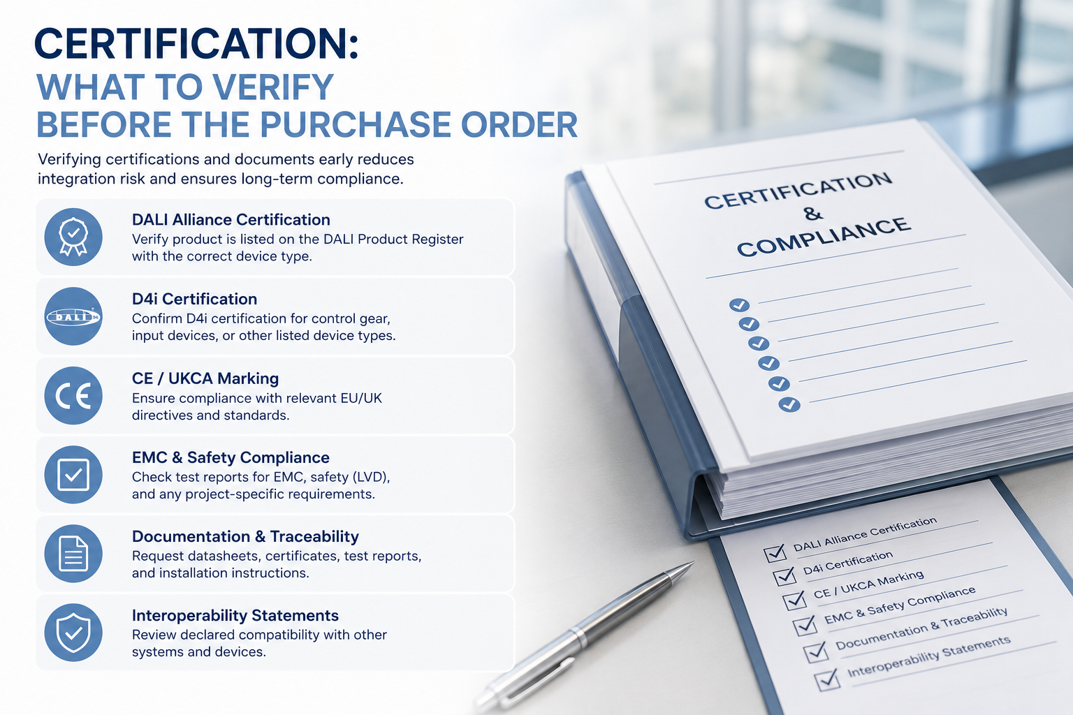
Zhaga states that the interoperability promise requires certified products on both sides of the interface. A certified luminaire paired with a non-certified node may still operate, but the project should not describe that combination as verified Zhaga-D4i interoperability. Zhaga Book 18 smart interface
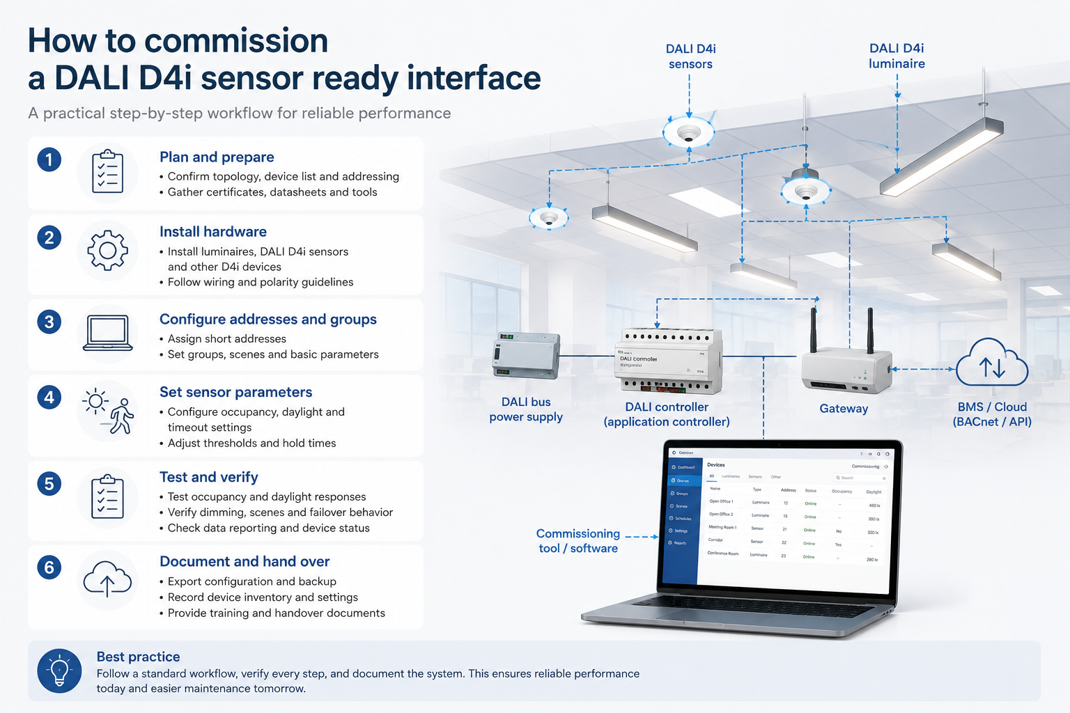
Commissioning should test the interface as a control and data point, along with the lamp response.
Compare each installed driver, receptacle, sensor and wireless node with the approved schedule. Record model numbers, firmware versions, serial numbers, mounting position and the D4i or Zhaga-D4i certification reference.
Inspect the plug and receptacle for full engagement, correct orientation, seal compression and mechanical stability. Confirm that the sensor has a clear field of view and that the mounting position matches the approved coverage plan. In outdoor applications, check the sealing and cable entry details after installation.
Use the selected commissioning tool to discover the driver and control device. Assign a stable asset ID that includes building, floor, zone and luminaire location. Store the identifier in the project record and in the management platform.
Test occupancy detection, timeout, fade time, daylight threshold, dimming level, manual override and scheduled scenes. Test the boundary of each zone. A sensor can communicate correctly while still covering the wrong area or triggering adjacent luminaires.
Confirm that the system can read the intended luminaire data, energy data and diagnostics. Simulate or document a control-device offline event, driver fault and gateway communication loss. Each event should identify the affected asset and show a timestamp.
Where a gateway or BMS connection exists, confirm point names, units, update intervals, alarm priorities and loss-of-communication behavior. Make sure a gateway failure does not disable the local lighting response required by the project.
Deliver the final device list, interface drawings, commissioning settings, firmware versions, test results, warranty information and replacement guidance. Facility teams need this record when a sensor or communication node reaches the end of its service life.
Test group | Minimum acceptance evidence |
Installation | Photo or inspection record showing the correct interface and secure mounting |
Device identity | Luminaire ID, driver ID, sensor or node ID, firmware and location |
Occupancy control | Detection test, timeout, fade time and zone response |
Daylight control | Threshold, dimming response and window-side zone test |
DALI communication | Successful discovery, addressing and control command response |
Energy and diagnostics | Readable values or documented reason a data point is unavailable |
Network path | Gateway discovery, point list, update interval and alarm test |
Resilience | Local control during gateway or network interruption |
Handover | As-built drawings, settings, manuals and replacement requirements |
This record changes the project conversation from “the sensor is installed” to “the interface, control logic and data path have been verified.” It also gives the facility team evidence for future maintenance and retrofit decisions.
DALI D4i sensor ready interfaces make the strongest business case when a project values modular luminaires, occupancy and daylight control, energy visibility, remote management or staged upgrades. They add specification and commissioning work, but they also make the system easier to document and maintain when the team verifies the complete interface chain.
For an OEM luminaire, retrofit or commercial building project, start with the driver model, the required sensor function and the future data path. LumiEasy can help review the driver, mounting method, sensor strategy, wireless control requirements, gateway need and commissioning logic before the equipment schedule is finalized. D4i Sensor Ready Lighting Control Solution for Commercial Lighting
A DALI D4i sensor ready luminaire needs a D4i driver, a compatible electrical and communication path, and a mechanical connection for a luminaire-mounted sensor or control device. A complete design also defines the sensor function, power supply, device type, commissioning method and any gateway or BMS connection.
No. D4i defines digital control, power and data requirements for intelligent luminaires and control devices. Zhaga-D4i adds a standardized Zhaga mechanical interface and a joint certification approach for compatible luminaires and nodes. The project should specify the relevant Zhaga Book and the certified products on both sides.
DALI Part 351 defines requirements for D4i luminaire-mounted control devices, including device types A through D, power consumption and priority behavior. It covers devices such as movement sensors, light sensors, timers and wireless network lighting controllers.
Zhaga Book 18 primarily supports outdoor luminaire interfaces and aligns with D4i device types A and B. Zhaga Book 20 addresses indoor luminaire-mounted control devices and aligns with types C and D. Confirm the Book and device type in the equipment schedule.
No. Local sensor-based occupancy or daylight control can work without a gateway when the driver and control device support the required logic. Projects need a gateway for remote monitoring, central scheduling, cloud access, multi-site management or BMS integration.
Check the exact driver and control-device entries in the DALI Alliance Product Database, then verify the luminaire and node certification in the Zhaga database where applicable. Match the Book, device type, pinout, power requirements, firmware and commissioning tool before installation.
Test physical fit, device discovery, addressing, occupancy response, daylight response, dimming, energy and diagnostic data, gateway point mapping and communication-loss behavior. Record the result against a stable luminaire asset ID and include the settings in the handover package.
Related news
DALI D4i Sensor Ready Interfaces
D4i Sensor Ready Lighting Control Solution
DALI D4i Compatibility Sensor Ready Standards


)
)
)
)

+86 15899791249

+86 755 2955 3313


Address: Huafeng No.1 Science and Technology Park, Sanwei, Bao'an District, Shenzhen, Guangdong, China.
