

Time:2026-08-17
Modern industrial manufacturing plants, automated logistics hubs, cleanrooms, and heavy fabrication facilities are undergoing a digital transformation. Energy efficiency regulations, corporate sustainability goals, and rising electricity tariffs require facility engineers to move beyond static, binary lighting systems. Traditional lighting controls—such as basic 0-10V analog dimming or non-communicating legacy DALI systems—are no longer sufficient for high-density industrial environments that demand real-time telemetry, predictive maintenance, and seamless sensor integration.
The introduction of DALI D4i sensor ready interfaces marks an evolutionary leap in smart industrial lighting architecture. Extension standards developed by the Digital Illumination Interface Alliance (DiiA) under the IEC 62386 umbrella turn LED high-bay fixtures, linear low-bay units, and floodlights from passive illumination devices into intelligent, data-generating IoT nodes.
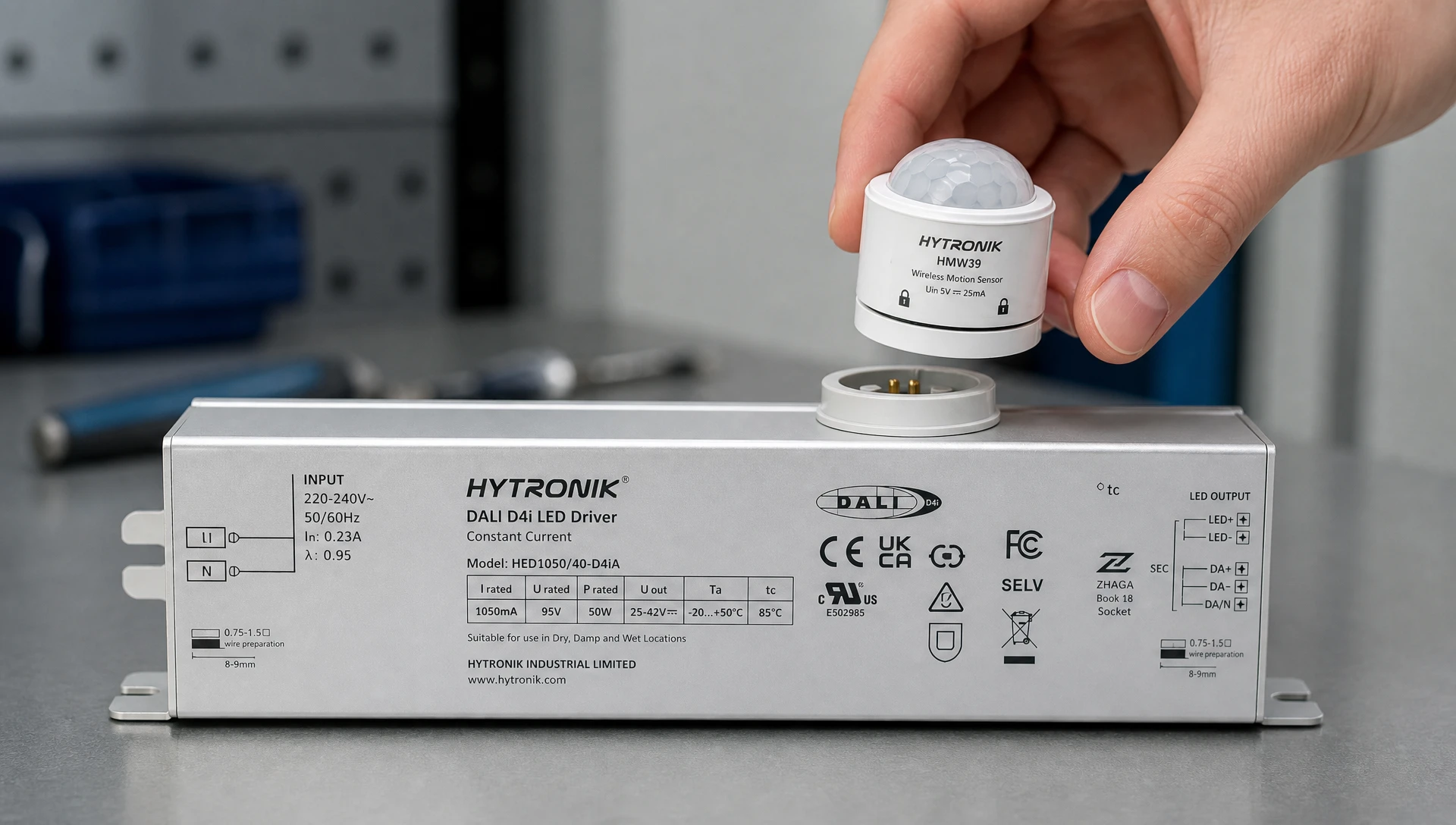
By integrating standardized power supplies, memory banks, and sensor interfaces directly into the LED driver, factory owners can mount wireless occupancy sensors, daylight harvesting photocells, and environmental monitors using plug-and-play sockets without adding complex external wiring or auxiliary power units. Understanding how these standardized interfaces drive the
To appreciate the value of DALI D4i sensor ready interfaces, engineering teams must understand the technical limitations of earlier control protocols. Legacy DALI-1 and standard DALI-2 systems required a standalone central bus power supply (typically delivering 16V DC at up to 250mA) to power the communication bus. Furthermore, auxiliary devices—such as wireless radios, microwave motion sensors, or Bluetooth Mesh nodes—demanded dedicated AC/DC power supplies, adding cost, physical bulk, and failure points inside the luminaire housing.
D4i resolves these physical constraints by embedding power generation and standardized data reporting directly within the LED driver. Under the hood, D4i is built upon four foundational DiiA specification standards:
D4i drivers feature an integrated DALI bus power supply that delivers power directly to the 2-wire DALI bus lines connected to the luminaire's sensor socket. This eliminates the need for a separate external bus power supply unit, simplifying fixture wiring and lowering total component count.
Part 251 defines a dedicated memory bank inside the driver that stores critical luminaire asset information during manufacturing. Factory technicians or automated BMS platforms can query this memory bank via the DALI interface to extract:
OEM Manufacturer ID and GTIN (Global Trade Item Number).
Rated luminaire wattage, initial lumen output, and CCT/CRI specifications.
Light distribution type, housing dimensions, and serial numbers.
Part 252 introduces standardized, real-time energy reporting directly from the driver’s internal power metering circuitry. Plant energy managers can access accurate electrical telemetry without installing secondary energy meters:
Active energy (kWh) and active power (W) consumption with ±1% to ±5% accuracy.
Apparent power (VA), reactive power (VAR), and operational power factor.
Part 253 enables true predictive maintenance by continuously recording operational stress factors and failure indicators inside the luminaire:
Total cumulative driver and LED operational runtime hours.
Driver internal temperature logs, peak temperature thresholds, and thermal derating events.
LED light source failure codes (short circuit, open circuit, load mismatch).
AC mains over-voltage, under-voltage, and transient surge counters.
Certain high-performance sensors—such as long-range microwave radar sensors, cellular IoT gateways, or edge computing nodes—require more electrical power than the standard DALI bus can deliver. D4i driver specifications include an auxiliary 24V DC power supply (capable of supplying 3W continuous load, with peak surges up to 6W) dedicated solely to powering sophisticated sensor nodes mounted to the fixture shell.
Achieving true "Sensor Ready" functionality requires both a standardized digital protocol and a universal physical socket interface. In industrial and commercial applications, two primary mechanical socket standards dominate the landscape: Zhaga Book 18 and NEMA ANSI C136.41.
Developed specifically for digital, low-voltage smart lighting environments, Zhaga Book 18 defines a compact, 4-pin receptacle that mounts directly through a standard 20mm knockout on the luminaire housing.
Pin 1: 24V DC Auxiliary Power (+24V AUX).
Pin 2: DALI- / Negative Return (GND).
Pin 3: DALI+ / Positive Communication & Bus Power.
Pin 4: General Purpose I/O (or logical expansion).
Because Zhaga Book 18 carries only low-voltage DC signals (24V DC and 16V DC DALI bus), it eliminates high-voltage AC wiring near the sensor head. The socket incorporates an IP66/IP67 mechanical twist-lock mechanism, allowing plant maintenance crews to snap in or exchange sensor modules in seconds without opening the sealed IP65 driver compartment or exposing high-voltage terminal blocks.
Originally created for outdoor roadway lighting, the NEMA 7-pin receptacle includes three high-voltage AC contacts (Line, Neutral, Load) alongside four low-voltage signal pads (0-10V or DALI). While still prevalent in outdoor loading docks, parking areas, and heavy industrial yards, NEMA sockets are larger and more expensive due to internal high-voltage creepage and clearance requirements.
| Interface Property | Zhaga Book 18 Socket | NEMA ANSI C136.41 Socket | Hardwired Cable Gland |
| Primary Voltage Level | Low Voltage DC (24V / 16V) | High Voltage AC + DC Signal | High Voltage AC / DC Signal |
| Pin Count | 4-Pin Compact receptacle | 7-Pin Heavy receptacle | Variable Terminal Block |
| Physical Diameter | ~30 mm (Minimal footprint) | ~76 mm (Large footprint) | Requires cable gland opening |
| IP Water/Dust Rating | IP66 / IP67 (Toolless twist lock) | IP66 (Twist lock) | IP65 / IP66 (Depends on gland) |
| Field Swappability | Hot-swappable in 5 seconds | Toolless swappable | Requires qualified electrician |
| Best Application | High-bay indoor plants, cleanrooms | External docks, perimeter yards | Fixed-function non-smart fixtures |
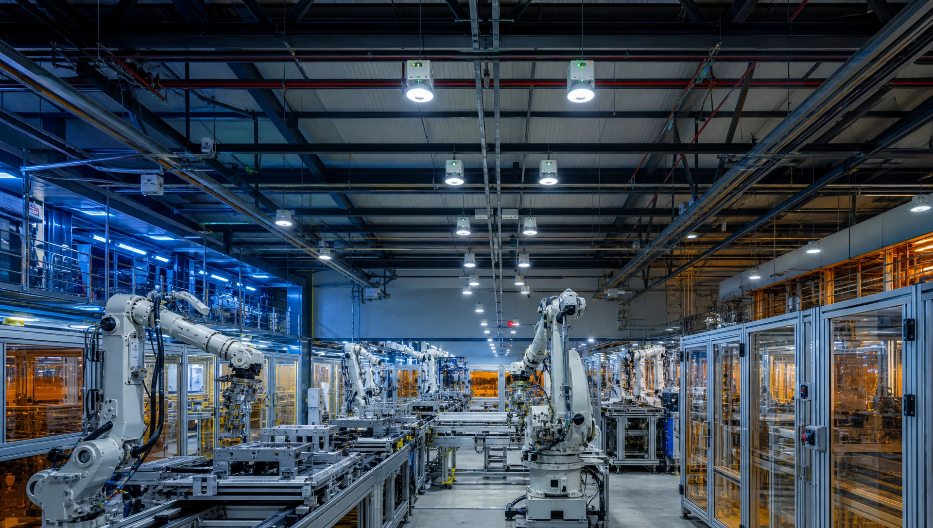
Industrial facilities present harsh, complex operating conditions that severely test lighting control systems. The combination of DALI D4i drivers and standardized sensor sockets provides targeted solutions across diverse factory zones.
Storage aisles in modern distribution centers experience sporadic forklift traffic. Running 200W LED high-bay fixtures continuously at 100% output in unoccupied aisles wastes enormous amounts of energy.
D4i Implementation: Each high-bay fixture is fitted with a Zhaga Book 18 high-ceiling microwave radar sensor powered directly via the driver's integrated DALI bus (Part 250).
Operational Outcome: When a forklift enters an aisle, the sensor detects movement at heights up to 15 meters and triggers the D4i driver to ramp illumination from a 10% standby level to 100% in under 300 milliseconds. When the aisle clears, the fixture automatically dims back to standby mode. Real-time power consumption during these transitions is continuously recorded via DALI Part 252 memory banks.
Assembly environments with large skylights or glass curtain walls benefit from daylight harvesting. However, traditional 0-10V daylight sensors require manual calibration and cannot report operational status back to central facility dashboards.
D4i Implementation: Multi-technology sensors (PIR + Daylight Harvesting + Bluetooth Mesh) are plugged into Zhaga Book 18 sockets on linear low-bay fixtures.
Operational Outcome: The sensor measures ambient daylight entering the production floor and dynamically adjusts the LED driver dimming level to maintain a constant 500 Lux target on working surfaces. Concurrently, the Bluetooth radio draws 24V AUX power to relay driver thermal health data (Part 253) to the plant's central Building Management System (BMS).
Cleanrooms require sealed, smooth surfaces that prevent dust accumulation and withstand aggressive chemical washdowns. Opening luminaire housings to service control electronics risks contaminating the sterile environment.
D4i Implementation: Flush-mounted Zhaga Book 18 sockets with IP67 rubber gaskets are factory-installed on the underside of recessed cleanroom troffers.
Operational Outcome: Environmental sensors or wireless nodes are installed or upgraded from below the ceiling plane without breaching the cleanroom seal or disturbing production lines.
Proper physical wiring and logical configuration are essential when deploying DALI D4i sensor ready interfaces in sprawling industrial plants. Thanks to D4i's polarity-free bus topology and built-in bus power supplies, physical installation labor is reduced by up to 60% compared to traditional wired control systems.
AC Mains Input Connection: Connect incoming line power (100–277V AC) to the primary terminal block of the DALI D4i driver. Ensure proper equipment grounding to protect sensitive internal digital logic from industrial surge transients.
Internal Socket Wiring: Route the low-voltage DC leads from the driver output terminals directly to the Zhaga Book 18 socket terminals:
Connect Driver AUX +24V to Socket Pin 1.
Connect Driver DALI - to Socket Pin 2.
Connect Driver DALI + to Socket Pin 3.
Leave Pin 4 open or connect to optional logical control inputs as dictated by the sensor specification.
Physical Sensor Mounting: Align the alignment keys of the Zhaga Book 18 sensor module with the socket keyways on the exterior of the luminaire housing. Push gently inward and twist clockwise 45 degrees until the spring-loaded detent snaps firmly into the locked IP66 position.
Logical Commissioning & Memory Querying: Apply AC mains power. The integrated D4i bus power supply automatically activates, powering the attached sensor node within 500 milliseconds. Commissioning technicians can now connect via a handheld DALI programming wand or wireless mesh gateway to auto-discover fixture addresses and verify memory bank parameters.
For comprehensive commissioning guidelines, addressing protocols, and multi-gateway mapping procedures, refer to our detailed
When presenting lighting control proposals to corporate capital expenditure (CapEx) committees, engineering leads must justify technology choices based on verifiable technical and operational metrics.
| Architectural Parameter | 0-10V Analog Dimming | Standard DALI-2 Protocol | DALI D4i Sensor Ready Interface |
| Communication Direction | Unidirectional (Control only) | Bidirectional (Control & basic status) | Bidirectional Full Telemetry |
| Integrated Bus Power | None (External power required) | Requires external DALI bus PSU | Embedded inside LED Driver (Part 250) |
| Auxiliary DC Power | None | Rare (Requires separate module) | Standard 24V DC AUX supply (3W/6W) |
| Energy Measurement | None (Requires external meter) | Optional / Non-standardized | Built-in ±1-5% Accuracy (Part 252) |
| Asset Tracking Data | None | None | Stored GTIN, Wattage, Lumens (Part 251) |
| Predictive Diagnostics | None | Basic fault flag only | Runtime, Temp, Voltage Logs (Part 253) |
| Socket Standard Support | Hardwired analog controls | Terminal block wiring | Standard Zhaga Book 18 / NEMA sockets |
| Commissioning Speed | Fast (Manual tuning) | Moderate (Addressing required) | Ultra-Fast (Plug-and-play auto-discovery) |
Factory floors are challenging electrical environments. High-power variable frequency drives (VFDs), heavy induction motors, arc welding equipment, and switching power supplies generate high levels of electromagnetic interference (EMI), voltage sags, and high-frequency harmonic distortion along AC power lines.
Sources of Industrial EMI Noise & D4i Defense Layers:
[VFD / Heavy Motors] ---> Harmonics on Line ---> [Isolated Driver Differential Filter]
[Arc Welders]        ---> Transient Voltage  ---> [10kV/20kV Heavy Surge Protector]
[RF Interference]    ---> Airborne Noise     ---> [Shielded Twist-Lock Sensor Socket]
DALI Bus Noise Immunity: The DALI communication protocol uses high-voltage signal swings (Nominal 16V DC: High level between 9.5V and 22.5V; Low level between -6.5V and +4.5V) and a low data transmission rate (1,200 baud). This low frequency makes D4i communication exceptionally resistant to high-frequency electromagnetic noise generated by nearby VFDs or heavy machinery.
Surge Protection Isolation: Industrial high-bay luminaires installed in heavy manufacturing plants should combine D4i drivers with dedicated 10kV or 20kV surge protective devices (SPD) installed upstream on the AC input lines. This prevents lightning strikes and heavy load-switching transients from passing into the driver's low-voltage DC AUX power rails.
Electrostatic Discharge (ESD) Protection at the Socket: Zhaga Book 18 sockets feature recessed, shrouded copper contacts that prevent maintenance personnel from discharging static electricity directly into the driver's microcontrollers when hot-swapping sensor heads on the shop floor.
Investing in DALI D4i sensor ready interfaces yields clear financial returns by combining automated energy reduction with substantial maintenance labor savings.
Facility Size: 15,000 square meter heavy machinery manufacturing plant.
Fixture Count: 300 units of 200W Industrial LED High-Bays (Total Connected Load: 60 kW).
Operating Hours: 24/7 continuous operation (8,760 hours per year).
Blended Energy Cost: $0.16 per kWh.
Baseline Energy Consumption (Unmanaged Fixtures running at 100%):
60 kW x 8,760 Hours = 525,600 kWh / Year
525,600 kWh x $0.16 = $84,096 Annual Electricity Expense

Managed Energy Consumption (D4i Sensor-Ready System):
- Occupancy sensing dimming in storage & secondary aisles: 35% overall power reduction.
- Daylight harvesting in perimeter bays: 15% overall power reduction.
- Total Combined Energy Savings: 50% Reduction in kWh.

Managed Annual Power Consumption = 262,800 kWh / Year
Managed Annual Electricity Expense = $42,048

Direct Electricity Savings: $42,048 per year!
Beyond direct energy reduction, D4i Part 253 diagnostic data eliminates emergency troubleshooting calls:
Targeted Lamp Servicing: Maintenance teams receive automated alerts specifying the exact fixture location, driver serial number, and failure code (e.g., "Bay 4 High-Bay #12 - Over-Temperature Warning") before the fixture experiences catastrophic failure.
Reduced Scissor-Lift Rentals: Technicians bring the exact replacement driver or sensor head on the first trip, avoiding diagnostic lift rentals. Maintenance labor expenses drop by an estimated $8,500 annually.
Total Combined Annual Savings = $42,048 (Energy) + $8,500 (Maintenance) = $50,548 / Year
Total System Upgrade Premium Payback Period = 11.4 Months
Before issuing purchase orders or releasing lighting specifications for industrial facilities, procurement managers should verify hardware compliance against this 8-point technical checklist:
DiiA D4i Official Certification: Confirm that specified LED drivers carry official D4i certification from the Digital Illumination Interface Alliance, verifying compliance with Parts 250, 251, 252, and 253.
Integrated Bus Power Capability: Ensure the driver's integrated DALI bus power supply provides at least 50mA to 250mA of guaranteed bus current to power connected sensors without voltage drops.
24V DC AUX Power Budget: Verify that the driver provides a dedicated 24V DC auxiliary power output with at least 3W continuous capacity (or 6W peak) to power high-draw wireless mesh gateways or radar sensors.
Physical Socket Standards: Specify IP66/IP67 rated Zhaga Book 18 receptacles with UV-stabilized, high-impact polycarbonate housings for indoor plants, or NEMA 7-pin sockets for exterior areas.
Operating Temperature Envelope: Ensure drivers and sensor sockets are rated for harsh ambient industrial temperatures (-40°C to +70°C) encountered near high factory ceilings.
Immunity & Surge Ratings: Mandate minimum 6kV/10kV surge immunity on the driver input terminals, with optional external 20kV SPDs for heavy industrial bays.
Data Memory Pre-Loading: Require lighting OEMs to pre-program luminaire asset data (Part 251 memory banks) during factory assembly to enable instant auto-commissioning upon arrival at the project site.
Manufacturer Technical Support & Warranty: Partner with an established lighting control manufacturer that offers comprehensive engineering schematics, custom driver configuration, and a minimum 5-year commercial warranty.
Integrating DALI D4i sensor ready interfaces transforms factory lighting from a static overhead cost into an intelligent, data-driven operational asset. By combining embedded DALI bus power, standardized 24V AUX supplies, and plug-and-play Zhaga Book 18 sockets with real-time energy metering (Part 252) and predictive diagnostics (Part 253), facility managers can achieve up to 50% energy savings while dramatically slashing maintenance overhead.
Whether you are retrofitting a legacy manufacturing facility, specifying high-bay luminaires as an OEM fixture builder, or designing a smart warehouse control architecture, partnering with an experienced smart control manufacturer is key to project success.
Ready to upgrade your industrial luminaires with certified DALI D4i drivers, Zhaga sensor sockets, and smart wireless control gateways? Contact our technical engineering team through the official
A1: Yes. D4i is fully backward compatible with standard DALI-2 systems. When connected to a standard DALI-2 controller, the D4i driver will respond to standard dimming commands, while its integrated bus power supply can be toggled or managed according to system design requirements.
A2: Zhaga Book 18 is a compact, 4-pin low-voltage DC socket designed specifically for digital protocols like DALI D4i. Unlike simple 0-10V analog connections, Zhaga Book 18 enables bidirectional digital communication, powering smart sensors while simultaneously reading real-time energy metering (Part 252) and diagnostic data (Part 253) directly from the driver.
A3: LumiEasy provides end-to-end technical support for industrial lighting projects, including custom D4i driver parameter pre-programming, schematic design reviews, Zhaga socket assembly validation, and high-performance wireless gateway integration tailored to meet your facility's exact requirements.


)
)
)
)

+86 15899791249

+86 755 2955 3313


Address: Huafeng No.1 Science and Technology Park, Sanwei, Bao'an District, Shenzhen, Guangdong, China.
