

Time:2026-07-15
Industrial manufacturing facilities operate within highly complex electrical environments. Unlike clean commercial office spaces, a factory power infrastructure is subjected to continuous stress, heavy inductive loads, and volatile supply variations. Within these ecosystems, automated lighting networks and facility management controls rely heavily on hardwired occupancy, motion, and daylight sensors to maintain optimal operating efficiency.
However, a recurring issue for facility engineers and electrical contractors is premature sensor failure, erratic switching behavior, or unexpected system downtime. These problems are rarely caused by defective sensor mechanics; instead, they stem from a failure to match the electrical characteristics of the building with the specific hardwired sensor voltage requirements of the control hardware.
When deploying automated commercial networks, understanding the precise relationship between supply line voltage, device tolerances, and grid fluctuations is critical. Miscalculating these variables can lead to overheating, electrical fires, or fried microprocessors, resulting in expensive unplanned operational maintenance.
This comprehensive technical guide evaluates the hardware engineering principles, electrical grid integration strategies, wiring safety margins, and deployment frameworks necessary to align industrial sensor systems with factory power realities.
Before specifying hardware or reviewing electrical schematics, facility managers must understand the structural differences between line voltage and low voltage sensor systems. Both topologies have a distinct place on the factory floor, but their input requirements and wiring setups are completely different.
Line voltage sensors connect directly to the building’s primary electrical distribution grid without an intermediate transformer. In heavy industrial settings across North America, Europe, and Asia, this typically requires the sensor to handle direct inputs ranging from 120V up to 277V, or even 480V in three-phase systems.
Primary Advantage: Simplicity of architecture. Because the sensor operates directly on mains power, it contains its own internal mechanical or solid-state relay to switch the lighting load on and off. There is no need for external power packs or separate low-voltage enclosures.
Engineering Challenge: Because the high-voltage lines run directly into the sensor housing, the internal components are directly exposed to any electrical noise or surges on the grid. This requires highly robust internal insulation, wider trace spacing on the circuit board, and advanced heat dissipation design to ensure a long operational lifespan.
Low voltage sensors operate on a isolated DC power supply, typically between 12V and 24V DC. These units do not connect directly to the main power lines. Instead, they link to an external power pack that steps down the facility’s mains voltage to a safe, low-voltage direct current.
Primary Advantage: Enhanced configuration flexibility and field safety. Low-voltage signal wires can be routed through standard conduits without the rigid protective shielding required for high-voltage lines. This allows engineers to easily link multiple sensors in parallel to manage complex, wide-area high-bay warehouse layouts.
Engineering Challenge: This approach requires installing external power packs throughout the ceiling structure, adding complexity to the initial system layout and increasing the total number of physical hardware components that need tracking.
| Technical Parameter | Line Voltage Sensors | Low Voltage Sensors |
| Direct Power Input | 120V, 227V, 277V, or 347V AC | 12V to 24V DC |
| Internal Switching Mechanism | Built-in mechanical or solid-state relay | Sends low-current signal to external relay |
| Conduit Isolation Requirements | High; requires full high-voltage enclosure protection | Low; Class 2 safety wiring circuits |
| Exposure to Grid Fluctuations | High; requires robust internal surge isolation | Low; isolated by the primary power pack transformer |
| Optimal Application Space | Standard manufacturing blocks and isolated zones | Large open-plan plants and high-bay logistics centers |
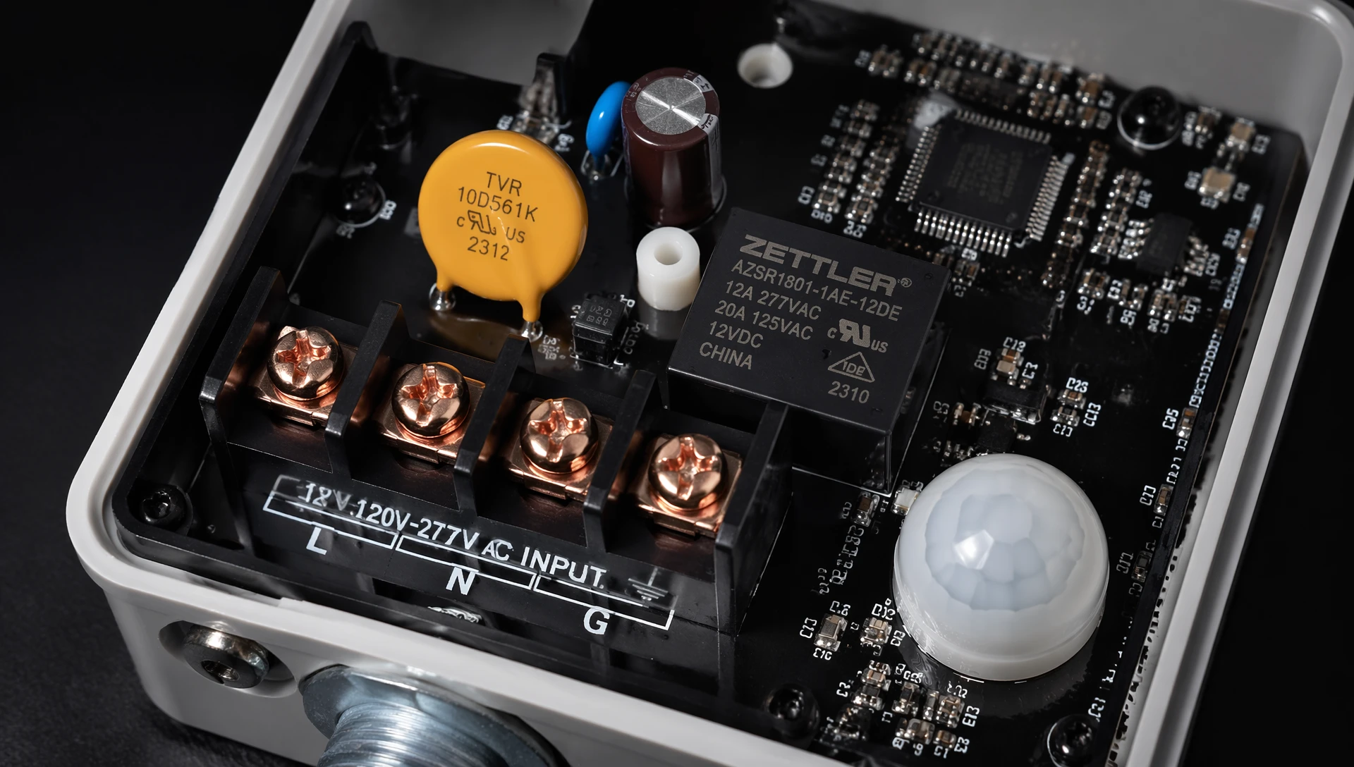
Modern global manufacturing demands versatile components. To streamline procurement and reduce spare parts inventory, industrial operators prefer sensors featuring universal voltage inputs. However, universal capability requires careful attention to system limits during installation.
High-end sensors use internal switched-mode power supplies (SMPS) that automatically adapt to incoming voltages, typically accepting any input from 120V to 277V AC at either 50Hz or 60Hz. The internal electronics automatically adjust the duty cycle of their switching transistors to maintain a stable internal DC voltage for the motion-sensing microchips, regardless of whether the unit is wired to a 120V utility line or a high-phase 277V lighting circuit.
However, operating a universal sensor near the top of its voltage rating introduces additional thermal challenges. When connected to a 277V system, the internal power components generate more heat than when running at 120V. If the sensor is mounted in a high-temperature factory ceiling where ambient heat traps exceed 55°C, this extra internal thermal stress can shorten the lifespan of the electrolytic capacitors, leading to premature device failure.
In heavy industrial centers—such as automotive assembly plants, foundries, and paper mills—lighting grids are often run on high-voltage circuits like 347V in Canada or 480V three-phase systems in the United States. This reduces the current draw and allows long wire runs with minimal line losses.
Standard universal sensors will fail instantly if connected directly to these high-voltage lines. For these configurations, facility engineers must deploy dedicated high-voltage sensors specifically rated for 347V/480V inputs, or install step-down autotransformers ahead of the sensor control nodes. Using transformers adds cost and takes up physical space, but it protects the sensitive sensory microprocessors from high-voltage damage.
Industrial electrical grids are notoriously unstable. The continuous starting and stopping of high-power equipment creates constant electrical noise and voltage shifts that can easily disrupt unprotected control systems.
When a massive inductive load—such as a 100-horsepower CNC milling motor or an overhead crane—shuts down, the sudden collapse of its magnetic field forces a massive electrical surge back into the facility's power lines. These transient voltage spikes can easily exceed 1,000 volts for a fraction of a second.
[Mains Distribution Bus] ───> [Heavy Inductive Motor Shuts Off] ───> [Transient Spike Generated]
                                                                            │
                                                                            ▼
[Destructive High-Voltage Wave] <─── [No Internal Protection] <─── [Travels Down Lighting Line]
                                                                            │
                                                                            ▼
[Protected Control Node] <─── [Clamp Spike Safety Buffer] <─── [Metal Oxide Varistor (MOV)]
If a sensor lacks robust internal protection, these spikes can punch through the insulation of its internal transformer or weld its mechanical relay contacts together, permanently locking the connected lights into an "always-on" state. To prevent this, industrial-grade sensors must include integrated surge protection—such as heavy-duty metal oxide varistors (MOVs)—capable of clamping high-voltage spikes before they reach the sensitive internal control circuits.
Conversely, when large industrial equipment starts up, it draws a massive amount of inrush current, causing a temporary voltage drop (a phase sag or brownout) across the local lighting grid. If a facility's nominal 277V line drops below 240V during these events, a poorly engineered sensor may lose its internal hold current. This causes its internal switching relay to drop out, leading to momentary lighting blackouts that disrupt workers on the plant floor.
Standard Industrial Power Line Nominal: 277V AC
├── High Fluctuation Ceiling (+10% Buffer): 304.7V AC  --> (Max Safe Absorption Limit)
├── Nominal Voltage Baseline: 277.0V AC
└── Low Fluctuation Floor (-10% Buffer): 249.3V AC   --> (Min Safe Operational Limit)

Critical Alert Zone (Drop below 240V): Causes sensor relay dropout and floor blackouts.
High-quality automated sensors are engineered with a flexible $\pm 10\%$ voltage tolerance window. This allows a device set for a 277V circuit to safely operate anywhere from 249V up to 305V, ensuring stable performance even during severe plant power drops.
In large-scale manufacturing facilities and distribution centers, long wire runs are common. When power lines stretch over hundreds of meters from the main electrical panel to a sensor node, the inherent resistance of the wire causes a gradual drop in voltage along the run.
Voltage drop is a direct function of the wire's length, its cross-sectional area, and the current load passing through it. While an individual sensor draws very little standby current, the cumulative load of a long series of line-voltage fixtures wired down the same branch circuit can cause a significant drop in voltage by the time it reaches the end of the line.
If the calculated voltage drop at the furthest sensor node exceeds 3% to 5% of the nominal line voltage, the device will receive a weak, unstable supply. This can cause the sensor to reboot continuously, lose its programmed time-delay settings, or fail to engage its internal switching relay.
To minimize line losses and maintain solid system stability, installation teams must follow strict wire gauge guidelines based on the total distance of the run:
Standard Localized Branch Circuits (Under 30 Meters): 18 AWG copper wire is generally sufficient for low-voltage sensor lines, while 14 AWG wire is standard for line-voltage lighting circuits.
Extended Facility Runs (30 to 100 Meters): Electrical teams should upgrade line-voltage control loops to 12 AWG copper wire to offset resistance buildup over the longer distance.
Long-Distance Industrial Control Buses (Greater than 100 Meters): For very long distances, running high-voltage mains lines is inefficient. Instead, engineers should transition to low-voltage sensor networks running on thick, shielded 16 AWG Class 2 control lines, or deploy a localized digital bus like DALI or BACnet.
A critical interface point in any modern industrial lighting system is the connection between the control sensor and the high-efficiency LED drivers. If the sensor's voltage output does not align with the input requirements of the LED driver, the system will not function correctly.
Modern commercial LED drivers are designed to work across a wide range of input voltages. When integrating a hardwired sensor to control these drivers, the installer must ensure that both the sensor and the driver are powered from the same phase and voltage source.
Wiring a 120V sensor to control a group of LED drivers running on a 277V circuit without using an isolating relay pack will destroy both devices instantly and create a serious high-voltage shock hazard for maintenance teams.
For details on optimizing sensor installations directly on commercial fixtures, check out the comprehensive
While LED fixtures consume less power during steady operation than old-fashioned high-intensity discharge (HID) lamps, they draw a massive, instantaneous surge of current the moment they are turned on. This inrush current occurs as the internal capacitors in the LED drivers charge up, often peaking at over 100 times the normal operating current for a few microseconds.
[Sensor Relay Switch Closes]
             │
             ▼
  (0 to 2 Microseconds)
[Massive Capacitor Charge Surge] ───> Peaks at 100x Normal Operating Current
             │
             ▼
     [Unprotected Relay] ───────> Standard contacts arc and weld shut (Permanent Failure)
             │
             ▼
[LumiEasy Zero-Crossing Relay] ─> Waits for AC wave to cross 0V point before switching
             │
             ▼
[Safe Current Inrush Level] ────> Clean engagement with zero component wear
If a line-voltage sensor uses a standard mechanical relay, this intense current surge causes an electrical arc across the contact points. Over time, this arcing welds the contacts together, causing the sensor to fail in the closed position so the lights cannot be turned off. Industrial-grade sensors prevent this by using advanced zero-crossing switching logic, which waits until the alternating current wave hits zero volts before closing the relay, completely eliminating destructive arcing.
Deploying a reliable, plant-wide control network requires a structured, step-by-step installation and testing workflow. Skipping validation steps during setup often leads to difficult troubleshooting issues down the road.
Before unboxing hardware or mounting sensors to the ceiling, electrical teams should perform a thorough grid analysis using a true-RMS digital multimeter. This assessment must track several key metrics:
Phase-to-Neutral Voltages: Verify that the actual voltage matches the nominal rating on the sensor's spec sheet under both full-load and no-load conditions.
Total Harmonic Distortion (THD): High levels of harmonic noise from heavy factory equipment can cause internal power supplies to overheat.
Ground-to-Neutral Voltage: A high reading here indicates a weak or poorly grounded neutral line, which can inject electrical noise into low-voltage control loops and cause false sensor triggers.
Once the initial power audit is complete, installation teams should follow a strict, sequential process to ensure a safe and successful deployment.
Step 1: Complete Pre-Installation Power Audit
        (Measure true-RMS voltage and confirm ground stability)
               │
               ▼
Step 2: Lock Out / Tag Out Primary Circuit Breaker
        (Verify zero voltage present with an insulation tester)
               │
               ▼
Step 3: Route Main Power and Control Line Cabling
        (Follow specified AWG requirements to minimize voltage drop)
               │
               ▼
Step 4: Mount Sensor and Seal Housing Seals
        (Ensure IP67 seals are properly seated against dust and moisture)
               │
               ▼
Step 5: Re-Energize Circuit and Run Full Functional Testing
        (Verify zero-crossing function and check low-voltage signal ranges)
First, lock out and tag out the primary circuit breaker, using a verified insulation tester to confirm the lines are completely dead. Next, route the main power and control line cabling, ensuring the wire gauge is correctly matched to the length of the run to prevent voltage drops.
Mount the sensor securely and verify that all IP67 environmental seals are properly seated to keep out dust and moisture. Finally, re-energize the circuit and run full functional testing, checking the zero-crossing function and verifying that low-voltage signal outputs remain stable across the entire control loop.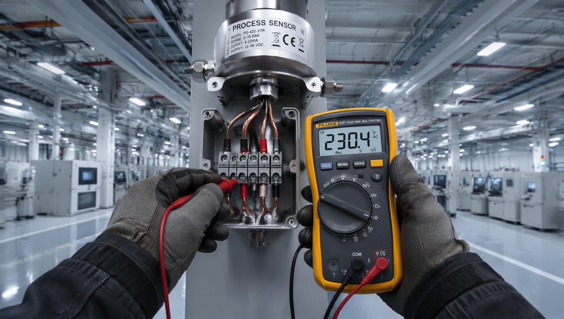
A1: If the supply voltage drops below the sensor's rated threshold, the device will lose its internal hold current. This causes the internal switching relay to open unexpectedly, shutting off connected lights and disrupting factory operations. Low voltage can also cause the sensor's internal microcontroller to constantly reboot, clearing its programmed time delays.
A2: No. National electrical safety codes strictly forbid running low-voltage Class 2 control lines in the same conduit as high-voltage mains wiring unless the low-voltage wires use specialized insulation rated for the maximum voltage present in the conduit. Running them together also introduces electromagnetic interference that can cause false sensor triggers.
A3: LumiEasy industrial sensors feature integrated zero-crossing switching logic. The sensor's microprocessor constantly tracks the incoming AC power wave and waits to close the internal contact points until the exact microsecond the voltage curve crosses zero volts. This prevents electrical arcing, protects the contacts, and extends the life of the system.
Optimizing a large manufacturing facility requires strong technical expertise and rugged, reliable hardware. Upgrading from basic, unprotected retail sensors to hardened, industrial-grade control networks helps eliminate unexpected downtime, reduce electrical maintenance costs, and provide a safe visual environment for production teams.
LumiEasy designs and manufactures high-performance industrial lighting controls and integrated sensor networks built to withstand the realities of heavy manufacturing grids. Our products feature wide voltage tolerance options, heavy-duty surge protection, and advanced zero-crossing technology to ensure flawless operation across complex factory layouts.
Protect your facility's infrastructure from electrical failures and unnecessary energy waste. Explore our complete line of industrial hardware options by speaking with our technical engineering team. To request a detailed project quote or discuss custom integration requirements for your facility, visit the official


)
)
)
)

+86 15899791249

+86 755 2955 3313


Address: Huafeng No.1 Science and Technology Park, Sanwei, Bao'an District, Shenzhen, Guangdong, China.
