

Time:2026-07-14
Industrial manufacturing infrastructures operate under strict operational mandates where utility expenses directly dictate bottom-line profitability. Across large-scale production facilities, heavy assembly plants, and global logistics hubs, commercial illumination grids represent a massive portion of fixed electrical overhead—frequently consuming up to 40% of a plant’s total energy footprint. Plant directors, facility operations engineers, and systems integrators are constantly searching for ways to cut these expenses without compromising plant floor safety, worker productivity, or assembly line accuracy.
Traditional automated lighting strategies rely on crude operational schedules or rigid zone sub-metering. These legacy setups often cause extreme energy waste, running high-output luminaires at maximum capacity even when natural ambient sunlight floods the floor through industrial skylights. The path to true operational efficiency requires transitioning to responsive, data-driven daylight harvesting control architectures driven by an industrial-grade linear light sensor.
This enterprise-level whitepaper provides a technical evaluation of the hardware engineering, environmental durability protocols, mathematical optimization frameworks, and IoT data pipeline strategies needed to deploy responsive sensor networks across heavy industrial environments.
An industrial-grade linear light sensor is fundamentally different from a standard consumer photocell or a simple localized motion detector. It is a highly specialized optoelectronic instrument designed to capture, process, and output continuous ambient illumination data across an extended linear physical footprint.
At the core of a high-performance linear sensor is an advanced silicon photodiode array. Unlike single-point sensors that detect light within a narrow, conical spot—making them highly vulnerable to localized reflections or temporary obstructions—a linear array captures a broader, elongated swath of light. This geometry is essential for industrial high-bay configurations and continuous-run linear fixtures, as it balances out minor visual variances across the floor.
The hardware processing pathway functions as a precise sequential system. Raw light first contacts the ambient illumination layer, where it immediately passes through an advanced optical filter designed to match the CIE photopic curve. This curve represents the human eye's natural sensitivity to different light wavelengths under well-lit conditions. By filtering out non-visible infrared and ultraviolet spectra, the sensor reads the actual luminous environment exactly as a worker experiences it.
Once filtered, the light hits the internal silicon photodiode array, which routes the raw data into an internal PID control engine. This engine processes the metrics to generate a stable, real-time control signal. Depending on the system design, this signal is routed either through an analog interface delivering continuous 0-10V dimming feedback or a digital interface executing bi-directional DALI-2 telemetry to adjust the driver output smoothly.
The sensor converts this optical input into a stable analog or digital control signal:
Analog Frameworks: The hardware provides continuous 0-10V dimming feedback. A reading of 10V calls for maximum artificial output, while 0V or 1V signals the driver to dim down to its minimum resting state.
Digital Integration: The device communicates via a digital bus using protocols like DALI-2 (Digital Addressable Lighting Interface) or Modbus RTU. This allows it to transmit precise lux values, internal temperatures, and diagnostic alerts back to a central hub.
Stepped dimming setups cause sudden drops or jumps in light levels that distract assembly workers and create optical stress. A linear light sensor eliminates this issue through step-less, continuous dimming.
As natural skylight slowly increases throughout the morning, the sensor detects decimal-level shifts in lux. The onboard microcontroller runs a proportional-integral-derivative (PID) loop that smoothly lowers the artificial luminaire output. The human eye cannot perceive this gradual transition, ensuring a stable visual environment on the manufacturing floor.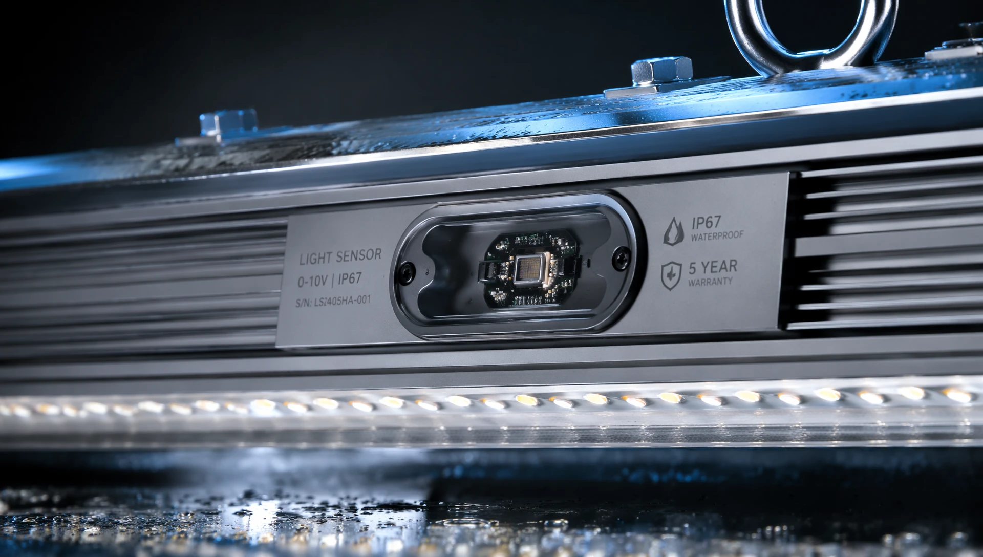
Industrial manufacturing zones are challenging environments for sensitive electronics. Standard commercial sensors often fail early due to high ambient temperatures, airborne contaminants, structural vibrations, and intense electrical noise. An industrial sensor must be explicitly engineered to withstand these variables.
Factory floors often generate fine dust particles, vaporized lubricants, or chemical mist from coolants and cutting fluids. If these elements accumulate on a sensor’s optical lens, they block light entry, leading to false low readings that force the system to waste energy by running the lights at maximum capacity.
To prevent this, advanced sensor enclosures feature an IP65 or IP67 ingress rating. The housings are made from UV-stabilized polycarbonate or anodized aluminum, with optical windows coated in hydrophobic and oleophobic materials. This treatment prevents oil mist and airborne dust from sticking to the surface, maintaining accurate lux readings with minimal maintenance.
Heavy industrial machinery—such as stamping presses, overhead cranes, and high-frequency milling stations—creates continuous structural vibrations across factory ceilings and support columns. This mechanical stress can crack standard solder joints on circuit boards. Industrial-grade sensors prevent this by using solid-state surface-mount components (SMD) locked in place with shock-absorbing potting compounds.
Furthermore, because factory ceilings can trap heat and reach high temperatures, the sensor's internal components must be rated for extended industrial temperatures (typically -40°C to +85°C) to prevent thermal drift and maintain accurate light readings.
| Environmental Stressor | Impact on Standard Sensors | Industrial Hardening Solution |
| Airborne Oil Mist / Dust | Attaches to lens; causes false low readings & energy waste. | IP67 rated enclosure with hydrophobic/oleophobic lens coating. |
| Mechanical Vibration | Cracks solder joints; causes intermittent component failure. | Solid-state SMD components secured with dampening potting compound. |
| High Thermal Traps | Causes signal drift; shortens sensor operational lifespan. | Component classification rated for continuous -40°C to +85°C exposure. |
| Electrical Line Noise | Creates light flickering and communication drops. | Optocoupled circuit isolation and integrated internal Faraday shielding. |
High-voltage machinery, variable frequency drives (VFDs), and large electric motors generate substantial electromagnetic fields. If a sensor is poorly shielded, this electrical noise can bleed into its signal wires, causing flickering, erratic dimming, or system communication drops.
High-quality sensors solve this through a multi-layered electrical protection strategy:
Differential Signaling: Utilizing twisted-pair wiring arrangements for digital buses to cancel out induced noise.
Optocoupled Isolation: Separating the sensitive low-voltage photodiode circuits from the main power lines to block high-voltage spikes.
Shielded Housings: Enclosing the sensor electronics in an internal metal Faraday cage to shield against radio-frequency interference (RFI).
Integrating a linear light sensor delivers a clear financial benefit by significantly cutting energy usage. To understand the return on investment (ROI), it helps to look at the calculations behind automated daylight harvesting.
Every manufacturing plant operates under specific lighting standards to ensure worker safety and quality control. For example, a heavy machinery assembly line might require a constant baseline target of 500 lux at the work surface. The total light measured on the active work surface is the direct mathematical sum of incoming natural daylight and the active artificial output generated by the facility's luminaires.
The primary goal of a daylight harvesting system is to maintain the total light exactly at the target level while minimizing the artificial contribution. The linear light sensor continuously calculates this balance by subtracting the measured natural daylight value from the pre-programmed target threshold. When natural daylight matches or exceeds the target level, the sensor signals the LED drivers to dim down to their lowest standby state or shut off entirely, capturing maximum energy savings.
Consider a medium-sized manufacturing facility operating a single warehouse block and two assembly zones:
Total Number of Fixtures: 400 linear high-bay units.
Power Rating per Fixture: 150 Watts at full output.
Total Baseline Lighting Load: 60,000 Watts (60 kW).
Operating Schedule: 14 hours per day, 300 days per year.
Electricity Rate: $0.12 per kWh.
Without smart sensor controls, the baseline annual energy usage is calculated by multiplying the sixty-kilowatt load by the fourteen daily operating hours, and then by the three hundred working days. This results in a baseline consumption of two hundred and fifty-two thousand kilowatt-hours per year. At a utility cost of twelve cents per kilowatt-hour, the annual baseline cost is exactly thirty thousand, two hundred and forty dollars.
When an industrial linear light sensor grid is deployed, historical performance data shows that natural daylight reduces the required artificial lighting output by an average of 45% across an average year. This optimization drops the annual energy consumption down to one hundred and thirty-eight thousand, six hundred kilowatt-hours. Multiplying this optimized volume by the twelve-cent utility rate reveals a new operational cost of sixteen thousand, six hundred and thirty-two dollars. The direct annual financial savings total thirteen thousand, six hundred and eight dollars.
By reducing the energy load, the facility also protects its power distribution infrastructure. Running LED fixtures at dimmed levels lowers the thermal strain on internal components, extending the operational life of the LED drivers and reducing future maintenance costs.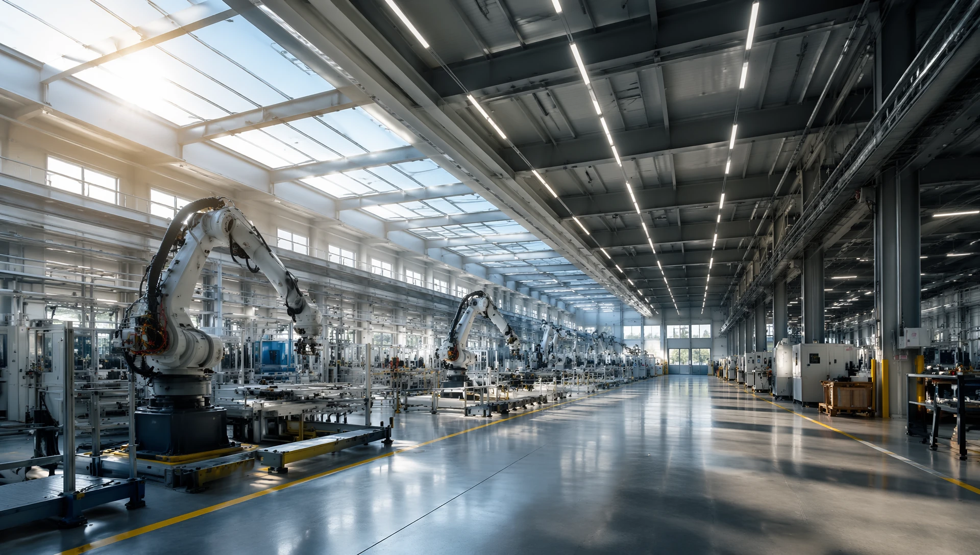
Achieving these energy savings requires careful placement and physical integration of the sensors. Poor positioning can lead to incorrect readings and limit the effectiveness of the entire system.
A common error is placing a light sensor directly beneath an artificial luminaire without proper calibration, or putting it in a spot where passing forklift traffic blocks its view. If the sensor is hit directly by light from the fixture it controls, it creates a feedback loop: it detects the bright light, dims the fixture down, senses the drop in light, and raises the brightness again. This loop causes continuous, erratic dimming.
To prevent these validation errors, industrial systems rely on two distinct spatial integration frameworks:
In an open-loop architectural configuration, the sensor node is physically positioned to face upward or outward, directly pointing toward an industrial skylight or large warehouse window wall. This orientation ensures that the photodiode array measures only the incoming natural daylight vector. The collected data is translated across the digital control bus straight to the LED driver unit, which dynamically scales the downward luminaire output. Because the sensor never reads the light produced by the internal fixture, feedback loops are physically impossible.
Conversely, a closed-loop architectural configuration mounts the sensor node facing downward, focused directly on the active manufacturing floor plane. In this layout, the sensor measures a combined ambient light mix consisting of reflected artificial illumination and natural daylight. The internal control processor constantly runs a dynamic correction loop, checking the ambient floor metrics against the programmed target lux value and adjusting the fixture output to maintain perfect balance.
Modern industrial facility managers prefer compact, integrated systems over bulky, externally wired sensors that clutter the ceiling and require complex installation. Integrating smart sensors directly into slim architectural channels or clean-room grade industrial housings provides a clean look and protects the components.
For projects requiring clean-room standards or sleek fixture designs, choosing low-profile hardware is essential. You can explore specialized integration techniques in this guide on
Modern industrial facilities are moving away from isolated hardware setups. Today's smart manufacturing plants connect their lighting controls into broader Internet of Things (IoT) networks and centralized Building Management Systems (BMS).
Advanced linear sensors do more than dim lights—they serve as data nodes across the factory ceiling. Every sensor continually tracks and transmits valuable operating metrics, including real-time ambient light levels, precise energy consumption metrics from individual fixtures, and critical device diagnostics like hardware temperature alerts.
This information travels through robust wireless mesh networks or wired control networks to an edge gateway. The transmission pipeline moves data from local sensor nodes across an optimized DALI bus or wireless mesh infrastructure directly to the gateway handler. From there, the data splits into two enterprise operational channels. Locally, it routes via BACnet protocols into the central Building Management System for real-time facility control. Simultaneously, it transmits encrypted MQTT or HTTPS data streams out to cloud-based energy analytics platforms to run predictive maintenance models.
By tracking energy usage and temperature trends over time, plant managers can implement predictive maintenance strategies. For instance, if a sensor reports that a fixture's internal operating temperature is rising while its light output drops, the system flags that unit for inspection before it actually fails. This allows maintenance teams to fix issues during scheduled downtime, avoiding unexpected disruptions on the production line.
A1: Yes. LumiEasy systems integrate advanced silicon photodiode arrays with custom mathematical filtering matching the CIE photopic response curve. This allows the sensor to isolate natural solar spectra from plant floor reflections, enabling precise baseline calibration.
A2: Every LumiEasy controller features programmable logic filters and built-in deadbands. When temporary weather changes occur, the system introduces a smooth ramp time rather than execution loops, protecting workers from disruptive, sudden shifts in brightness.
A3: LumiEasy heavy-industrial linear sensors are engineered with specialized narrow-angle optical lenses. This allows them to maintain precise lux tracking at installation heights reaching up to 15 meters (approx. 50 feet), making them perfect for high-bay warehouse layouts.
Optimizing a large manufacturing facility requires high-resolution operational visibility. Transitioning from legacy lighting networks to an advanced system built on verified sensor architectures helps eliminate energy waste, secure maximum utility rebates, and provide clear data for corporate sustainability audits.
LumiEasy manufactures ruggedized, high-efficiency industrial LED lighting systems and intelligent network controls designed specifically for heavy production environments. Our hardware solutions deliver exceptional metering accuracy, native protocol compliance, and secure wireless mesh connectivity tailored to the complex layouts of modern smart factories.
Don't leave valuable utility rebates and operational insights on the table. Discover optimized industrial components and system options by connecting with our technical consulting team. To request an enterprise-level project estimation or explore custom OEM options, connect with our technical consulting team via the official


)
)
)
)

+86 15899791249

+86 755 2955 3313


Address: Huafeng No.1 Science and Technology Park, Sanwei, Bao'an District, Shenzhen, Guangdong, China.
