

Time:2026-08-14
Industrial manufacturing plants, expansive logistics warehouses, cleanrooms, and high-bay fabrication facilities operate under constant pressure to minimize power consumption while maintaining optimal illumination for worker safety and precision quality control. In large-scale industrial facilities, traditional lighting controls—such as centralized electrical breaker panels or simple wall switches—are notoriously inefficient. Turning on an entire 50,000-square-foot production floor just to illuminate a single active assembly line wastes thousands of kilowatt-hours annually and drastically accelerates luminaire wear.
The deployment of a modern multi zone lighting remote system solves this fundamental challenge. By enabling wireless, granular control over distinct lighting zones—such as individual production bays, storage racks, inspection stations, and administrative annexes—facility managers can instantly tailor light levels to real-time operational demands.
Facility directors who are evaluating energy efficiency upgrades quickly realize the strategic importance of understanding
A multi zone lighting remote is a specialized wireless transmitter—available as a handheld unit, wall-mounted touch panel, or desktop master controller—designed to independently manage multiple groups (zones) of luminaires from a single interface. Unlike basic single-channel remotes that control all paired lights simultaneously, a multi-zone controller divides a lighting network into distinct logical channels (e.g., Zone 1, Zone 2, Zone 3, up to Zone 16 or more).
An industrial wireless lighting control system consists of three fundamental hardware layers:
The Wireless Transmitter (Remote Control / Touch Panel): Sends encoded Radio Frequency (RF) or wireless mesh signals containing target Zone IDs, brightness percentages, Color Temperature (CCT) settings, or pre-programmed scene recall triggers.
The Signal Receiver / Smart Driver Node: Connected directly to or embedded within the LED luminaires. Receives the wireless command and translates it into physical dimming protocols, such as 0-10V analog voltage, DALI-2 digital commands, or PWM (Pulse Width Modulation).
The Luminaire Array: High-bay LED lights, linear low-bay fixtures, task lights, or floodlights that execute the requested lighting state.
To design an effective factory lighting layout, engineering teams must distinguish between logical control terms:
Zone: A physical geographic area on the factory floor (e.g., "Packaging Line A").
Group: A collection of individual lighting receivers mapped to respond to the same command.
Channel: The specific RF frequency band or software address path used to prevent signal crosstalk between adjacent remote controls operating in the same facility.
By decentralizing lighting controls and allowing floor supervisors to adjust specific zones on the fly, plant managers are driving synergy across complex industrial facilities with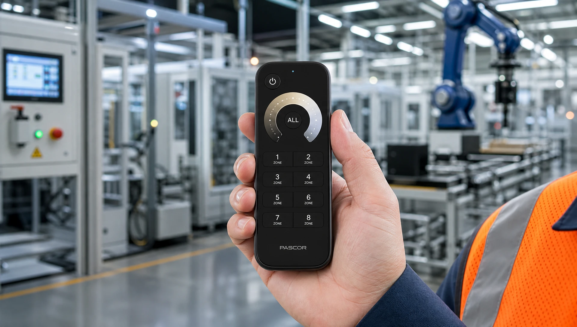
Factories are dynamic environments where lighting requirements vary continuously across different shifts, tasks, and plant zones. A multi-zone lighting remote empowers personnel to adapt illumination instantly without touching main distribution panels.
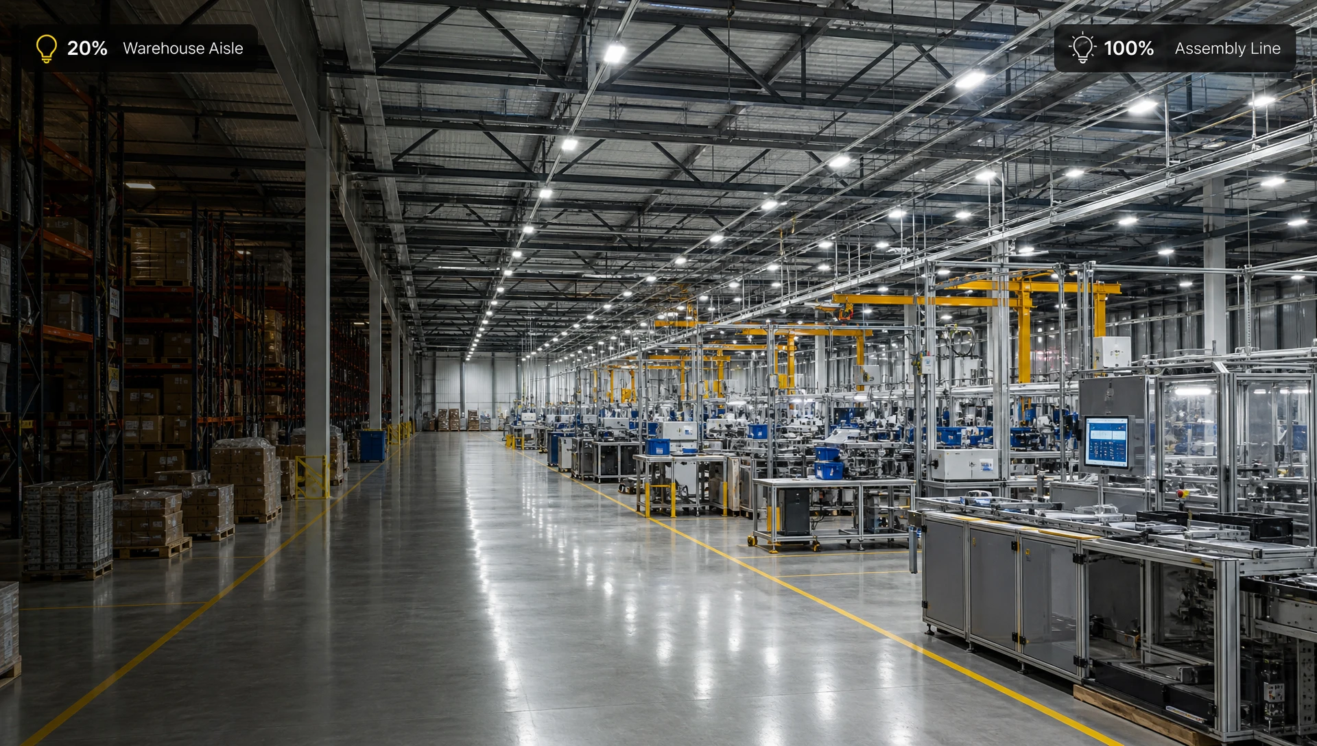
Assembly lines require bright, glare-free illumination (typically 500 to 750 Lux) during active production shifts to ensure accuracy and worker safety. However, during lunch breaks, shift handovers, or machine maintenance windows, running high-bays at 100% output is wasteful.
Multi-Zone Action: The floor supervisor uses Zone 1 on the remote to dim the active assembly line down to a 20% standby level during breaks, and presses a single "Work Scene" button to restore full 100% illumination when production resumes.
In high-bay logistics centers, storage aisles are only occupied when forklift drivers retrieve or store pallet inventory.
Multi-Zone Action: A multi-zone remote mapped to Zones 1 through 8 allows warehouse managers to adjust light levels aisle by aisle. Aisles undergoing inventory audits can be locked to 100% output, while unused aisles remain dimmed to 10% background ambient levels, integrating seamlessly with motion sensors.
Inspection stations require high Color Rendering Index (CRI > 90) and variable color temperature (CCT) tuning (3000K to 6000K) to detect surface defects, micro-cracks, or color variations in painted parts.
Multi-Zone Action: Inspectors use a dedicated CCT Multi-Zone Touch Remote (Zone 2) to toggle between warm and cool daylight spectrums, revealing subtle material defects that standard neutral lighting masks.
During non-operational night hours, facilities must maintain minimum egress lighting (50 to 100 Lux) for security personnel and safety compliance.
Multi-Zone Action: Pushing the "Night Master" button on an 8-zone master remote instantly sets all primary production zones to 0% while keeping peripheral exit pathways (Zone 4) at a safe 10% baseline output.
Selecting the wrong remote control hardware can lead to dropped signals, premature battery depletion, or physical equipment failure under harsh industrial conditions. Electrical engineers must evaluate the following specifications when procuring multi-zone remotes.
RF 2.4GHz Direct Wireless: The industry standard for localized group controls. Operates on worldwide license-free ISM bands. Delivers instantaneous touch response (< 10ms delay) and pairs directly with 2.4GHz receivers without requiring an internet gateway.
Sub-1GHz (433MHz / 868MHz / 915MHz): Offers superior obstacle penetration through concrete walls, steel racks, and heavy metal machinery. Ideal for sprawling industrial complexes where long line-of-sight distance is required.
Wireless Mesh (Zigbee 3.0 / Bluetooth Mesh): Nodes relay signals from one fixture to another, extending total control distance across thousands of square meters. Multi-zone remotes in mesh networks communicate with nearest nodes, routing commands across the entire network.
Industrial remotes must remain operational without frequent maintenance:
Coin-Cell Powered (CR2032 / CR2450): Suitable for low-frequency handheld remotes. High-efficiency RF controllers draw minimal standby current (< 2uA), extending battery life to 2–3 years under typical usage (20 button presses per day).
AAA Battery Powered Handhelds: Preferred for heavy-use floor managers. Easy to source and replace on-site without special tools.
AC/DC Hardwired Wall Panels: Mounted in control rooms or plant supervisor offices. Directly powered by 100-240V AC or 12-24V DC auxiliary lines, eliminating battery maintenance entirely while providing continuous backlighting.
IP Ratings: Standard office remotes (IP20) fail rapidly in industrial environments due to dust ingress or oil mist accumulation. For factory floors, select handheld remotes with IP54 to IP65 sealed rubber keypads or wall-mounted touch glass panels that resist dust, moisture, and chemical splashes.
Impact Resistance: Remotes used in manufacturing facilities should feature rubberized protective bumpers capable of surviving 1.5-meter drops onto concrete floors.
| Form Factor | Primary Use Case | Max Zone Capacity | Physical Power Source | Mounting / Portability |
| Handheld RF Remote | Shift supervisors walking floor bays | 4, 8, or 16 Zones | CR2032 / AAA Batteries | Portable with magnetic wall holder |
| Wall Glass Touch Panel | Fixed control point at bay entrance | 1, 2, or 4 Zones | 100-240V AC Mains / 24V DC | Flush-mount standard junction box |
| RF Rotary Dimmer Knob | Granular single/multi zone dimming | 1 or 2 Zones | CR2032 Battery / AC Mains | Surface mount or wall box insert |
| Central Master Desktop Remote | Main security or plant office | Up to 16 Zones + Scenes | USB-C Rechargeable / AC Plug | Desktop stand or console mounting |
Commissioning a multi-zone lighting control system requires a structured, step-by-step process to ensure each receiver node maps correctly to its assigned remote control zone button.
In factory high-bay setups, receivers/drivers are mounted 10 to 15 meters above the floor, making physical "Match Buttons" impossible to press. The Power-Up Match Protocol allows floor technicians to pair zones directly from the circuit breaker panel:
Isolate the Target Zone: Switch off the AC power line feeding the specific group of LED drivers intended for Zone 1. Keep power ON for all other zones.
Restore Power & Trigger Pairing: Switch the AC power back ON. Within 5 seconds of powering up, immediately press the desired Zone 1 "ON" button on the handheld multi-zone remote 3 times consecutively.
Confirm Pairing: The connected high-bay LED lights will flash 3 times slowly. This visual indicator confirms that all power-cycled drivers have successfully saved the Zone 1 RF address to their internal memory.
Repeat for Subsequent Zones: Power down the AC circuit for Zone 2, restore power, press the Zone 2 "ON" button 3 times, and verify the 3 flashes. Repeat until all physical zones are assigned.
When receivers are installed inside accessible low-voltage control cabinets:
Short-press the physical Match Key on the receiver unit. The indicator LED on the receiver will start blinking rapidly.
Immediately press the target Zone Button (e.g., Zone 3) on the multi-zone remote.
The receiver indicator LED will flash 5 times, confirming that Zone 3 pairing is locked in.
If a fixture is accidentally mapped to the wrong zone:
Power off the target AC circuit.
Restore power, and within 5 seconds, quickly press the Zone "ON" button or Master "ON" button 5 times consecutively.
The fixtures will flash 5 times rapidly, signaling that all saved RF remote addresses have been cleared.
Once initial pairing is complete, engineers can program advanced scene controls and group dynamics to streamline daily operations.
Industrial multi-zone remotes feature dedicated Scene Buttons (S1, S2, S3, S4) that allow operators to recall multi-zone configurations with a single press:
Adjust Individual Zones: Using the remote, set Zone 1 to 100% brightness, Zone 2 to 50% brightness, and Zone 3 to 10% standby output.
Save the Scene: Press and hold the S1 Button for 3 seconds until all connected luminaires blink once. The current multi-zone state is now saved to memory location Scene 1.
One-Touch Shift Transitions: At the end of a production shift, pressing S2 instantly dims the entire plant into "Break Mode" without needing to manually adjust individual zones one by one.
For multi-zone remotes managing Color Temperature (Tunable White) or RGBW accent lighting:
Synchronous Dimming: High-performance remotes feature automatic signal re-transmission. When the master brightness slider is dragged, the remote broadcasts a global sync frame ensuring that all paired zones dim in lockstep without visible flicker or latency drift between adjacent light fixtures.
Factories are harsh radio-frequency environments. Heavy electric motors, arc welders, variable frequency drives (VFDs), structural steel columns, and high-density metal storage racks can attenuate or bounce RF signals, leading to dropped commands or range degradation.
Elevate RF Receivers Above Structural Obstacles: Avoid mounting receiver units or external antennas directly behind thick steel I-beams or inside fully enclosed metal electrical boxes. Mount antennas underneath or extending below the ceiling plane to maintain clear line-of-sight paths.
Deploy Signal Power Repeaters / Mesh Amplifiers: In facilities exceeding 50 meters in length, insert dedicated RF signal repeaters midway down main aisles. Modern multi-zone receiver nodes feature automatic auto-forwarding technology, where each receiver automatically relays valid remote commands to neighboring nodes within a 30-meter radius.
Manage Wi-Fi & Bluetooth Frequency Coexistence: Standard 2.4GHz RF lighting remotes share spectrum with industrial IEEE 802.11 b/g/n Wi-Fi networks. To prevent signal blocking:
Configure plant Wi-Fi access points to use fixed channels Channel 1, Channel 6, or Channel 11.
Set the multi-zone lighting RF system to operate on frequency channels equivalent to Zigbee Channel 25 or 26, which sit in the guard band above Wi-Fi Channel 11.
Implementing multi-zone wireless remote control delivers measurable financial returns by replacing blanket 100% illumination with targeted, zone-specific lighting strategies.
Annual energy consumption for an unmanaged vs. multi-zone managed industrial lighting layout is calculated as:
Unmanaged Annual kWh = Total Connected Power (kW) x Total Plant Operating Hours
Managed Annual kWh = Sum of [ Zone Power (kW) x Zone Operating Hours x Average Dimming Level % ]
Baseline Equipment: 200 units of 200W LED High-Bay Fixtures = 40,000W (40 kW) total load.
Operating Schedule: 16 hours per day, 300 days per year = 4,800 operating hours annually.
Electricity Tariff: $0.15 per kWh.
Unmanaged Baseline Cost:
40 kW x 4,800 Hours = 192,000 kWh / Year
192,000 kWh x $0.15 = $28,800 Annual Electricity Cost

Multi-Zone Remote Managed System:
- Zone 1 (Active Assembly, 50% of plant): 20 kW running at 80% average output = 16 kW
- Zone 2 (Storage & Logistics, 30% of plant): 12 kW running at 30% average output = 3.6 kW
- Zone 3 (Auxiliary & Circulation, 20% of plant): 8 kW running at 20% average output = 1.6 kW
Managed Load = 21.2 kW total equivalent draw (47% load reduction)

Managed Annual Cost:
21.2 kW x 4,800 Hours = 101,760 kWh / Year
101,760 kWh x $0.15 = $15,264 Annual Electricity Cost

Total Financial Savings: $13,536 per year (47% direct power savings)
Hardware Investment payback period: Under 6 months!
| Cost / Project Component | Traditional Wired Circuit Switching | Wireless Multi-Zone Remote System |
| Control Cable Material Cost | High (Hundreds of meters of copper conduit) | Zero (100% Wireless RF Transmission) |
| Electrical Labor Hours | Extreme (Pulling wire through high ceilings) | Low (Plug-and-play driver connection) |
| Facility Down-Time | High (Production stopped during rewiring) | Minimal (Retrofit completed in active bays) |
| Re-zoning Flexibility | Impossible without physical rewiring | Instantaneous via software re-pairing |
| Maintenance Complexity | Complex cable fault-finding | Simple modular receiver replacement |
When commissioning multi-zone wireless lighting controls, field engineers may encounter operational anomalies. Use this systematic diagnostic matrix to isolate and resolve technical issues quickly.
| Fault / Error Symptom | Likely Root Cause | Field Diagnostic Step | Recommended Resolution |
| Zone 3 fixtures do not respond to remote commands | Fixtures lost RF pairing or receiver is unpowered. | Check if receiver LED illuminates; verify AC power supply voltage. | Re-execute Power-Up Pairing protocol for Zone 3. |
| Light fixtures flicker or flash intermittently during dimming | Incompatible driver dimming curve or 0-10V signal drop. | Measure 0-10V control wire DC voltage stability across DIM+ and DIM-. | Ensure receiver PWM/0-10V output matches driver dimming interface requirements. |
| Remote control range drops significantly inside the facility | High RF attenuation from metal walls or heavy battery drain. | Measure remote battery voltage (replace if < 2.6V DC for CR2032). | Install an RF repeater node or replace remote batteries. |
| Pressing Zone 1 button also turns on lights in Zone 2 | Duplicate address pairing saved in receiver memory. | Perform RF memory clear procedure on Zone 2 receivers. | Clear receiver memory and re-pair Zone 1 and Zone 2 independently. |
| Touch wall panel freezes or fails to light up | Unstable input power or static high-voltage surge. | Verify AC input voltage at terminal block; cycle main breaker power. | Power-cycle the touch panel; install surge protection on incoming line. |
Before procuring multi-zone lighting remotes for industrial facility retrofits, verify system requirements against this 8-point engineering checklist:
RF Protocol Compatibility: Confirm that remote output frequency (e.g., 2.4GHz RF, Zigbee 3.0) matches the onboard receiver chips in all specified LED drivers.
Zone Capacity Margin: Choose a remote with at least 25% more zone capacity than current plant layouts require (e.g., select an 8-zone remote even if currently utilizing 5 zones) to accommodate future factory expansion.
Enclosure Protection Rating: Ensure handheld remotes used on the shop floor carry an IP54 or higher dust/water resistance rating.
Battery & Power Availability: Verify whether wall-mounted touch controllers can be hardwired to local AC power or if battery-powered units are required for wireless placement.
Signal Obstacle Survey: Conduct a site survey to identify thick concrete firewalls or structural metal barriers that require RF signal repeaters.
Fail-Safe Emergency Mode: Ensure that if a remote control is misplaced or damaged, LED drivers default to 100% full brightness when power-cycled at the breaker, maintaining safety lighting.
Physical Wall Mounting Holders: Confirm that all handheld remotes include magnetic wall brackets or belt clips to prevent loss or physical damage on the factory floor.
Manufacturer Technical Support: Partner with an established smart lighting controller manufacturer that provides technical schematics, customized driver pre-configuration, and long-term warranty support.
Deploying a robust multi zone lighting remote architecture turns a static industrial lighting setup into a dynamic, energy-efficient operational asset. By dividing production bays, storage zones, inspection labs, and egress routes into independently controlled wireless zones, factory managers cut energy overhead by up to 50%, reduce installer labor costs, and streamline facility workflows.
Whether you are retrofitting a legacy manufacturing facility, upgrading a logistics warehouse, or developing custom OEM lighting control packages, working with an experienced controller manufacturer ensures seamless signal reliability and long-term performance.
Ready to optimize your industrial plant lighting with certified multi-zone RF remotes, wireless touch panels, and smart LED drivers? Contact our engineering specialists through the official
A1: Standard 2.4GHz RF handheld remotes offer a line-of-sight range of 30 to 50 meters in open factory bays. When paired with auto-forwarding receivers or mesh repeaters, signal range extends indefinitely across the facility as each receiver node re-transmits commands up to an additional 30 meters.
A2: Yes, provided the appropriate wireless receivers are installed at each fixture group. Multi-zone remotes broadcast universal RF or mesh control frames; an RF-to-0-10V receiver translates commands for analog drivers in Zone 1, while an RF-to-DALI receiver in Zone 2 controls digital DALI drivers simultaneously.
A3: LumiEasy multi-zone control systems utilize advanced frequency-hopping spread spectrum algorithms, robust RF power amplification, and multi-node auto-forwarding. This allows control signals to bypass dense steel structures and maintain rock-solid communication across high-interference manufacturing floors.


)
)
)
)

+86 15899791249

+86 755 2955 3313


Address: Huafeng No.1 Science and Technology Park, Sanwei, Bao'an District, Shenzhen, Guangdong, China.
