

Time:2026-09-01
Industrial manufacturing plants, logistics hubs, and processing facilities are rapidly transforming their physical infrastructure to meet rigorous energy efficiency standards, reduce carbon footprints, and achieve operational automation. A central component of this digital transformation is the modern smart lighting system. However, operating thousands of intelligent luminaires across sprawling plant floors presents a critical engineering challenge: bridging local fieldbus networks—such as Bluetooth Low Energy (BLE) Mesh, DALI-2, or Zigbee—with enterprise-level Building Management Systems (BMS), Supervisory Control and Data Acquisition (SCADA) platforms, and cloud telemetry databases.
Deploying a high-performance smart lighting gateway solves this connectivity bottleneck. Acting as an intelligent edge processor, a smart lighting gateway translates local wireless and wired lighting control protocols into enterprise IT/OT standards (including BACnet/IP, Modbus TCP, MQTT, and OPC UA), providing facility managers with centralized monitoring, automated energy management, and real-time operational diagnostics.
To withstand the severe operating conditions of industrial plants—such as high ambient temperatures, electromagnetic interference (EMI) from motor drives, and dirty power feeds—an industrial-grade smart lighting gateway requires specialized hardware engineering and edge processing capabilities.
The physical system architecture follows a three-tier operational hierarchy:
Enterprise Layer: Houses central cloud platforms, building management systems, and SCADA engines communicating over IT/OT protocols like BACnet/IP, Modbus TCP, and MQTT/TLS.
Gateway Hardware Core: Features a multi-core ARM processor, TPM 2.0 security chip, and local RAM to run edge-level protocol translation engines, telemetry caching routines, TLS encryption, and X.509 authentication protocols.
Field Node Layer: Manages localized high-bay LED luminaires, occupancy sensors, and daylight harvesting controllers via fieldbus interfaces including BLE 5.2 Mesh, DALI-2, and RS-485.
Processor Core: Multi-core ARM Cortex-A53 or Cortex-A7 industrial application processor operating at 1.2 GHz or higher, enabling local data aggregation, protocol translation, and real-time execution of control logic.
Memory & Storage: Minimum 1 GB DDR4 RAM combined with 8 GB or 16 GB eMMC industrial flash storage, capable of caching up to 90 days of local sensor telemetry during network outages.
Physical Communications Interfaces:
Dual 10/100/1000 Mbps RJ45 Ethernet ports with network separation (WAN/LAN isolation).
High-power Bluetooth Low Energy 5.2/5.3 radio transceiver with power amplifier (+20 dBm output) supporting over 300 active BLE Mesh nodes.
Dual RS-485 galvanically isolated serial ports for Modbus RTU communication.
Integrated dual-channel DALI-2 bus controllers providing power and signal control for up to 128 DALI addressable drivers.
Industrial Hardening: IP30 to IP66 metal enclosure with DIN-rail or wall-mounting hardware; operational temperature rating from -40°C to +70°C; 2 kV surge protection on power and communication lines.
Unlike basic pass-through bridges that depend entirely on active cloud connections, an advanced smart lighting gateway features autonomous edge intelligence. The edge processing engine runs localized routines directly on the device:
Autonomous Local Fallback: If cloud or BMS connectivity is disrupted, the gateway continues to execute scheduled dimming curves, daylight harvesting calculations, and occupancy-triggered switching locally without operational interruption.
Data Filtering and Aggregation: Instead of flooding enterprise networks with raw sensor reads every millisecond, the gateway filters noise, aggregates sensor data over user-defined time windows (e.g., 1-minute averages), and transmits only meaningful telemetry changes.
Local Event Engine: Executes fast-path automation rules across disparate protocols (e.g., triggering a DALI emergency light bank when a BLE vibration sensor reports an anomaly) with sub-10 millisecond response times.
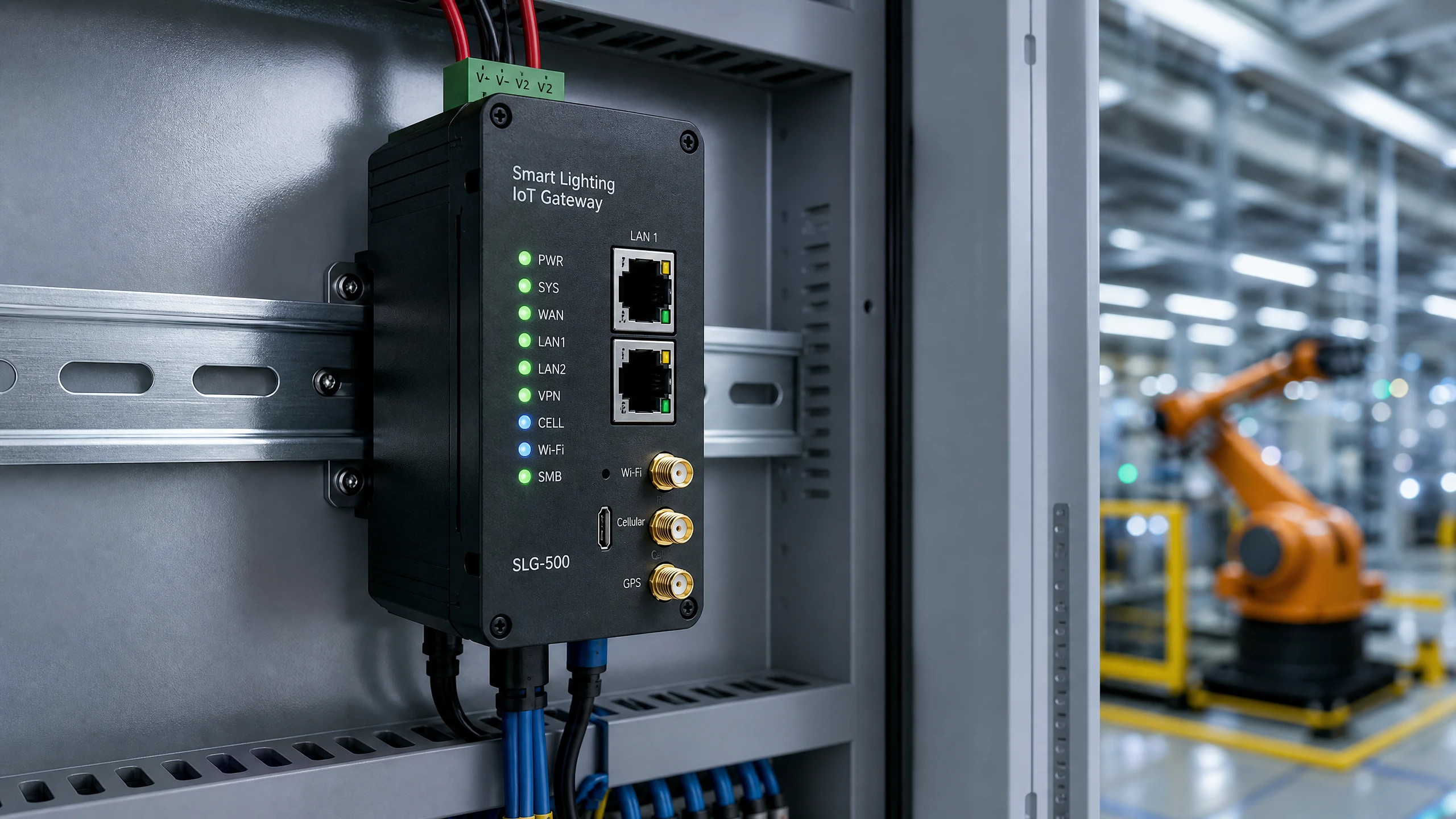
The primary operational mandate of a smart lighting gateway is bidirectionally translating field-level lighting protocols into enterprise IT and OT formats. This enables legacy building automation systems and modern cloud dashboards to control and monitor field devices effortlessly.
The gateway processes inbound field signals and translates them across multiple enterprise channels through a sequential three-step pipeline:
Inbound Field Payload Ingestion: Captures raw field telemetry, such as a BLE Mesh packet containing Node ID 0x01A4 reporting an ambient light level of 450 Lux.
Matrix Transformation Mapping: The translation engine simultaneously maps Node 0x01A4 to a BACnet Analog Input Object (AI:104), converts the 450 Lux value into Modbus Holding Register 40105, and formats the payload into a structured JSON string ({"node_id":"01A4","lux":450}).
Enterprise Outbound Distribution: Distributes the translated data streams to on-premise BMS via BACnet/IP, industrial SCADA systems via Modbus TCP, and corporate cloud analytics platforms via encrypted MQTT/TLS.
| Fieldbus Protocol (Inbound) | Gateway Processing Method | Enterprise Protocol (Outbound) | Primary Target Application |
| BLE Mesh | Decrypts mesh frames, extracts sensor attributes, maps to registers | BACnet/IP | Commercial Building Management Systems (Trane, Honeywell) |
| DALI-2 / D4i | Parses D4i memory bank telemetry (power, runtime, temperature) | Modbus TCP | Industrial SCADA Control Systems (Siemens, Rockwell) |
| Zigbee 3.0 | Converts Zigbee Cluster Library (ZCL) commands into JSON objects | MQTT / TLS | Cloud IoT Analytics Platforms (AWS IoT, Azure IoT) |
| Modbus RTU | Translates serial registers into standardized network data points | OPC UA | Advanced Industrial Automation & Industry 4.0 Engines |
When a BLE occupancy sensor detects motion on a factory bay floor, it broadcasts a BLE Mesh state message. The gateway receives this packet, decrypts it using the local Application Key (AppKey), and updates its internal status table.
Simultaneously, the gateway's protocol engine exposes this parameter to the enterprise IP network as a BACnet Binary Input (BI) object:
BLE Input Parameter: Occupancy State = Active (1)
BACnet Object Name: Bay3_Occupancy_Sensor
BACnet Object Type: BINARY_INPUT
BACnet Object Instance: 2004
Present Value: ACTIVE
Plant engineers can read about comprehensive multi-protocol architectures in our dedicated industry guide on
Determining the required number of smart lighting gateway units for a manufacturing or warehousing facility depends on node density, packet frequency, RF signal propagation, and data throughput limits.
Maximum BLE Mesh Nodes per Gateway: Up to 300 active nodes (luminaires, sensors, switches) under typical industrial operating parameters; up to 500 nodes in low-telemetry environments.
Maximum DALI Channels: Up to 2 physical channels (128 addressable DALI drivers total).
Maximum Concurrent BMS Connections: 16 simultaneous BACnet/IP client connections and 8 Modbus TCP master connections.
Upstream Telemetry Throughput: Up to 500 messages per second (msg/sec) via Ethernet.
To avoid network congestion and packet drops, network architects utilize mathematical traffic modeling formulas to determine the total upstream bandwidth required by a gateway deployment.
Formula: Bandwidth_Req = (N * (P_data + P_hdr) / T_interval) * (1 + Over_Factor)
Where:
Bandwidth_Req: Total upstream network bandwidth required (in Bytes per second, B/s).
N: Total number of connected field devices reporting to the gateway.
P_data: Raw payload size per sensor telemetry packet (e.g., 64 bytes for voltage, current, power factor, and temperature data).
P_hdr: Protocol transport header size (e.g., 54 bytes for standard TCP/IP + MQTT header overhead).
T_interval: Telemetry reporting interval per node (in seconds, e.g., 10 seconds).
Over_Factor: Safety margin for retransmissions and peak burst traffic (typically 0.25, representing a 25% overhead buffer).
Sample Calculation:
For a facility bay with N = 250 nodes, sending P_data = 64 bytes with P_hdr = 54 bytes every T_interval = 10 seconds:
Bandwidth_Req = (250 * (64 + 54) / 10) * (1 + 0.25)
Bandwidth_Req = (250 * 118 / 10) * 1.25
Bandwidth_Req = 2950 * 1.25 = 3687.5 Bytes/sec (~29.5 Kbps)
This calculation demonstrates that even with 250 connected industrial devices, a well-engineered smart lighting gateway maintains a very light network payload (~29.5 Kbps), making it suitable even for remote bandwidth-constrained LTE or satellite backup links.
Connecting factory floor equipment to corporate IT networks introduces potential cybersecurity risks. A robust smart lighting gateway acts as a secure boundary wall between field-level radio networks and corporate intranets, enforcing Zero-Trust security protocols across all layers.
To prevent unauthorized network intrusion, the gateway enforces a four-level Zero-Trust security hierarchy:
Cloud and WAN Protection: Encapsulates northbound data transfers using TLS 1.3 encrypted tunnels authenticated via X.509 device certificates.
Perimeter Isolation: Applies strict firewall rules and physical port isolation between WAN and LAN interfaces.
Hardware Security Core: Utilizes an onboard TPM 2.0 cryptographic coprocessor for AES-256 key storage and conducts secure boot checks with cryptographically signed firmware binaries.
Field Radio Security: Secures localized wireless traffic using AES-128-CCM encryption, managed network keys (NetKey), application keys (AppKey), and device keys (DevKey).
Hardware Security Module (TPM 2.0): An integrated cryptographic chip securely stores private keys, boot certificates, and encryption seeds, rendering the gateway immune to physical tampering or memory extraction attacks.
Secure Boot and Signed Firmware: The bootloader verifies the cryptographic signature of the operating system image before execution. Any unauthorized or tampered firmware binary is rejected automatically.
Dual-Net Network Isolation: Two physical RJ45 Ethernet controllers isolate the field-level lighting network from the enterprise corporate LAN. The gateway routes data payloads internally without creating a transparent network bridge, preventing unauthorized lateral movement by potential hackers.
Encrypted Outbound Telemetry: All northbound communication to cloud or remote servers is wrapped in TLS 1.3 encryption using X.509 client certificate authentication.
Role-Based Access Control (RBAC): Administrative interfaces (Web GUI, SSH, REST API) require multi-factor authentication and strict privilege management to prevent unauthorized configuration changes.
When covering extensive industrial plants exceeding 50,000 square meters, deploying a single gateway creates a single point of failure and risks radio packet saturation. System integrators utilize structured multi-gateway network topologies to guarantee scalability and full redundancy.
For large-scale facilities, a high-availability topology links an Enterprise Central BMS to a redundant pair of gateways over Ethernet BACnet/IP. Primary Gateway A oversees Subnet 1 (Bays 1–5), while Secondary Gateway B manages Subnet 2 (Bays 6–10). Both gateways maintain a continuous heartbeat synchronization link and share overlapping wireless mesh coverage, allowing either gateway to immediately take over field luminaire node management if the other experiences a power or connection failure.
Mesh Subnet Partitioning: Sprawling factory spaces are divided into logical subnets (e.g., Gateway 1 handles Machining Bay; Gateway 2 handles Warehousing). Each gateway manages a dedicated wireless channel and network key (NetKey) to eliminate cross-channel packet collisions.
High Availability & Failover Pairing: Critical manufacturing areas deploy dual gateways in a Primary-Secondary high-availability cluster. Gateways exchange continuous heartbeat signals over an isolated sync link. If the Primary gateway loses power, the Secondary gateway automatically assumes control of the field network within 3 seconds.
Inter-Gateway Synchronization: Gateways coordinate global time stamps and cross-zone lighting scenes using Network Time Protocol (NTP) or IEEE 1588 Precision Time Protocol (PTP), ensuring that shift-wide lighting adjustments occur simultaneously across all bays.
Deploying an industrial smart lighting gateway within an active manufacturing facility requires a systematic commissioning procedure to minimize plant downtime and ensure seamless software integration.
Mount the gateway inside an industrial control cabinet or directly on a cable tray standard using standard 35 mm DIN-rail clips.
Supply 24V DC auxiliary power (or connect a 802.3at Power-over-Ethernet Plus cable to WAN Port 1).
Connect external omnidirectional antennas to the BLE and Wi-Fi SMA connectors, ensuring antennas extend outside metal enclosures.
Connect an engineering laptop to LAN Port 2 using a standard Ethernet patch cable.
Access the gateway's embedded management console via HTTPS ([https://192.168.1.1](https://192.168.1.1)).
Configure static IP addresses, subnet masks, and default gateways for WAN Port 1 (Enterprise Network) and LAN Port 2 (Maintenance Field Network).
Update device passwords and upload the plant's security X.509 SSL certificates.
Initiate the field radio discovery engine via the gateway management console.
Scan for unprovisioned BLE luminaires, DALI drivers, and environmental sensors across the target plant zone.
Assign target devices to logical groups (e.g., Group_101_Production_Line_A) and bind control profiles (occupancy sensing, daylight harvesting, manual override).
Navigate to the Protocol Gateway Engine configuration tab.
Select target nodes and click Auto-Generate BACnet Objects to create corresponding Analog Inputs (AI), Binary Inputs (BI), and Analog Outputs (AO).
Export the BACnet Vendor MIB file or Modbus Register Address Table (.csv format) for integration into the central SCADA platform.
Import the generated Modbus register table into the central SCADA software (e.g., Ignition, Wonderware, or Siemens WinCC).
Execute bidirectional verification tests: toggle lighting output commands from the SCADA console and confirm that field luminaires respond within 50 milliseconds.
Simulate an Ethernet disconnect on WAN Port 1 to verify that local edge routines maintain daylight harvesting and motion detection functions without interruption.
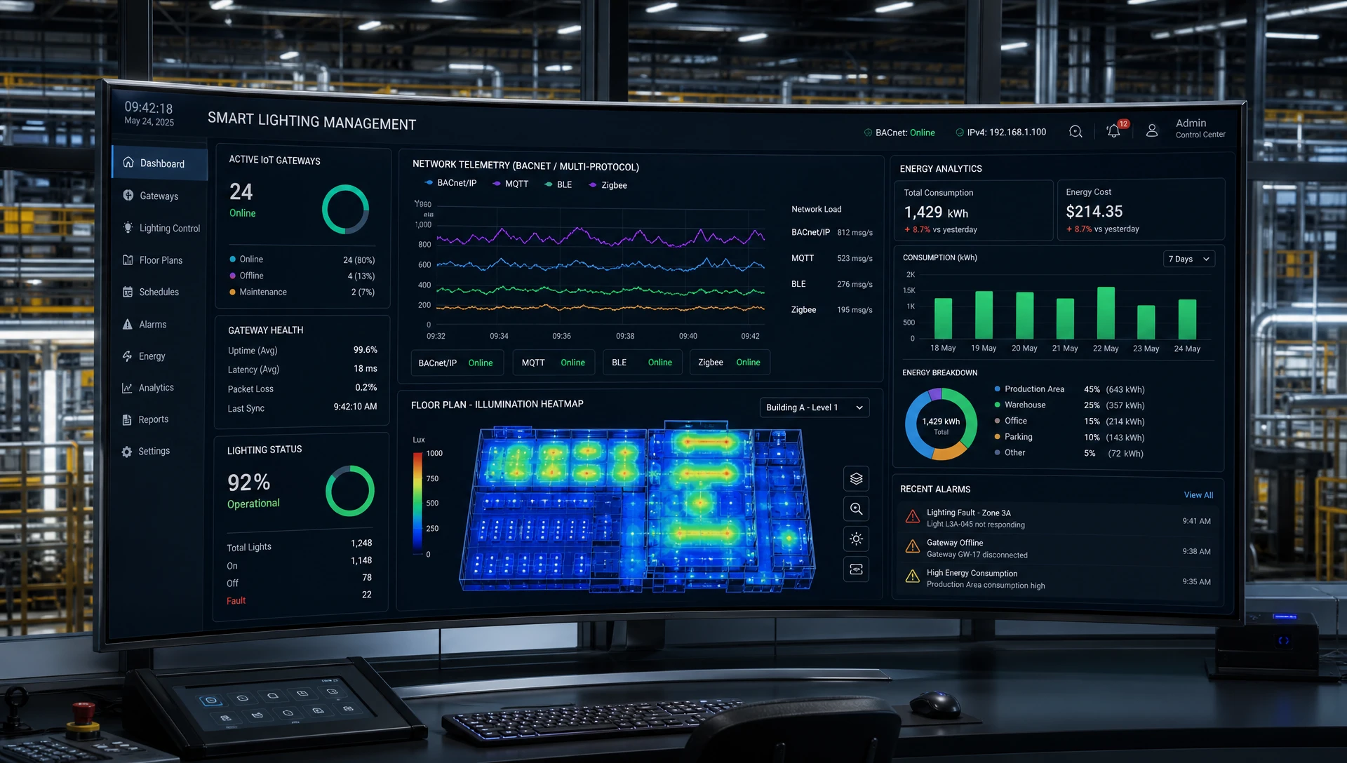
Implementing a smart lighting gateway transforms simple lighting fixtures into a data-rich asset management framework. To evaluate the commercial justification for plant retrofits, review the financial performance model below:
Facility Surface Area: 45,000 square meters (Automated Assembly Plant).
Lighting Infrastructure: 2,000 high-bay LED luminaires (150W each).
Operating Hours: 24/7/365 continuous operation (8,760 hours/year).
Industrial Electricity Tariff: $0.13 per kWh.
| Operational Metric | Unmanaged Standard LED System | Local Motion Sensor LED System | Smart Lighting Gateway Managed System |
| Installed Luminaire Wattage | 300,000 Watts (300 kW) | 300,000 Watts (300 kW) | 300,000 Watts (300 kW) |
| Average Load Profile | 100% Continuous (300 kW) | 70% Average (210 kW) | 30% Effective Load (90 kW) |
| Annual Power Consumption | 2,628,000 kWh | 1,839,600 kWh | 788,400 kWh |
| Annual Electricity Expense | $341,640 | $239,148 | $102,492 |
| Annual HVAC Thermal Offset Savings | $0 | $12,500 | $28,600 |
| Annual Maintenance & Servicing | $18,000 | $12,000 | $2,500 (Predictive Alerts) |
| Total Annual Operational Cost | $359,640 | $251,648 | $133,592 |
| Annual Net Savings vs Baseline | Baseline | $107,992 | $226,048 |
Total Gateway Hardware & Installation Investment: $68,000 (including 12 industrial smart lighting gateways, edge software licenses, and SCADA integration services).
Net Annual Operating Cost Savings: $226,048 per year.
Simple Payback Period: 3.6 months.
5-Year Net Return on Investment (ROI): 1,562%.
By leveraging automated task tuning, scheduled occupancy setbacks, daylight harvesting, and predictive driver failure alerts routed through a central smart lighting gateway, industrial operators achieve drastic reductions in total operating overhead.
If a LumiEasy smart lighting gateway loses main power or WAN network connectivity, all connected luminaires, occupancy sensors, and switches continue operating locally via decentralized BLE Mesh or DALI-2 protocols. Daylight harvesting, motion switching, and safety overrides run autonomously at the luminaire level without disruption.
A single industrial LumiEasy smart lighting gateway can actively manage up to 300 BLE Mesh devices (luminaires, sensors, switches) and up to 128 DALI-2 addressable drivers across dual physical channels. For larger manufacturing plants, multiple gateways can be clustered together to support tens of thousands of connected nodes seamlessly.
Yes. LumiEasy smart lighting gateways feature native hardware protocol conversion engines supporting BACnet/IP, Modbus TCP, Modbus RTU, and MQTT. They expose all field parameters—such as energy consumption, driver temperature, light levels, and motion states—directly as standard BACnet objects or Modbus registers compatible with major BMS and SCADA platforms.
Modernizing factory infrastructure with an intelligent wireless and wired control network optimizes energy consumption, reduces maintenance overhead, and delivers continuous operational analytics.
To review complete technical hardware data sheets, request custom network topology designs, or consult directly with our application engineers,


)
)
)
)

+86 15899791249

+86 755 2955 3313


Address: Huafeng No.1 Science and Technology Park, Sanwei, Bao'an District, Shenzhen, Guangdong, China.
