

Time:2026-09-02
High-bay industrial manufacturing facilities, automated assembly plants, and heavy processing warehouses consume vast amounts of electrical energy, with lighting accounting for 20% to 40% of total facility electricity overhead. Operating large-scale industrial luminaires at 100% continuous power regardless of shift schedules, ambient daylight availability, or physical floor occupancy creates severe financial waste and accelerates equipment degradation.
Integrating modern automated lighting controls eliminates unnecessary power consumption by dynamically adjusting illumination levels based on real-time environmental telemetry, production schedules, and occupancy patterns across industrial shop floors.
Evaluating industrial lighting infrastructure upgrades requires a clear engineering understanding of how an automated lighting controls system operates within complex manufacturing environments.
Unlike basic manual switching or isolated timer switches, an enterprise-grade automated lighting controls system forms a closed-loop cyber-physical architecture. The system continuously senses environmental variables, processes operational logic at the local edge or central controller, and sends precise dimming or switching signals to luminaire drivers.
The system operates through a continuous four-stage signal processing sequence:
Environmental Signal Acquisition: Field sensors (PIR, microwave radar, and photodiodes) continuously capture real-time motion and ambient lux telemetry.
Logic Processing Core: Distributed edge processors evaluate sensor data against local daylight harvesting schedules, astronomical time clocks, and safety override commands.
Control Output Execution: Processed control commands are transmitted across digital buses (DALI-2), analog control channels (0-10V), or zero-crossing power relays.
Luminaire Illumination Output: Dimmable high-bay LED luminaires and task lights dynamically adjust lumen output to maintain target illumination levels.
Primary Sensing Layer: Deploys industrial-grade Passive Infrared (PIR) sensors, high-frequency Microwave radar detectors, and dual-technology occupancy sensors alongside closed-loop digital photodiodes. These sensors capture motion and ambient light levels at mounting heights up to 20 meters.
Logic Processing Layer: Consists of distributed local controllers or centralized edge processors. The processing core executes preset schedule profiles, calculates daylight harvesting dimming curves, and evaluates override requests from emergency building systems.
Signal Transmission Layer: Transmits control instructions across physical wired channels (such as DALI-2 or 0-10V analog wiring) or secure wireless mesh protocols (such as Bluetooth Low Energy Mesh or Zigbee 3.0).
Luminaire Execution Layer: Receives dimming signals via smart LED drivers equipped with pulse-width modulation (PWM) or continuous current reduction (CCR) capabilities, smoothly adjusting fixture output from 100% down to 1% or completely turning off power via zero-crossing relays.
To explore how these hardware layers adapt across different facility topologies, review our comprehensive breakdown on
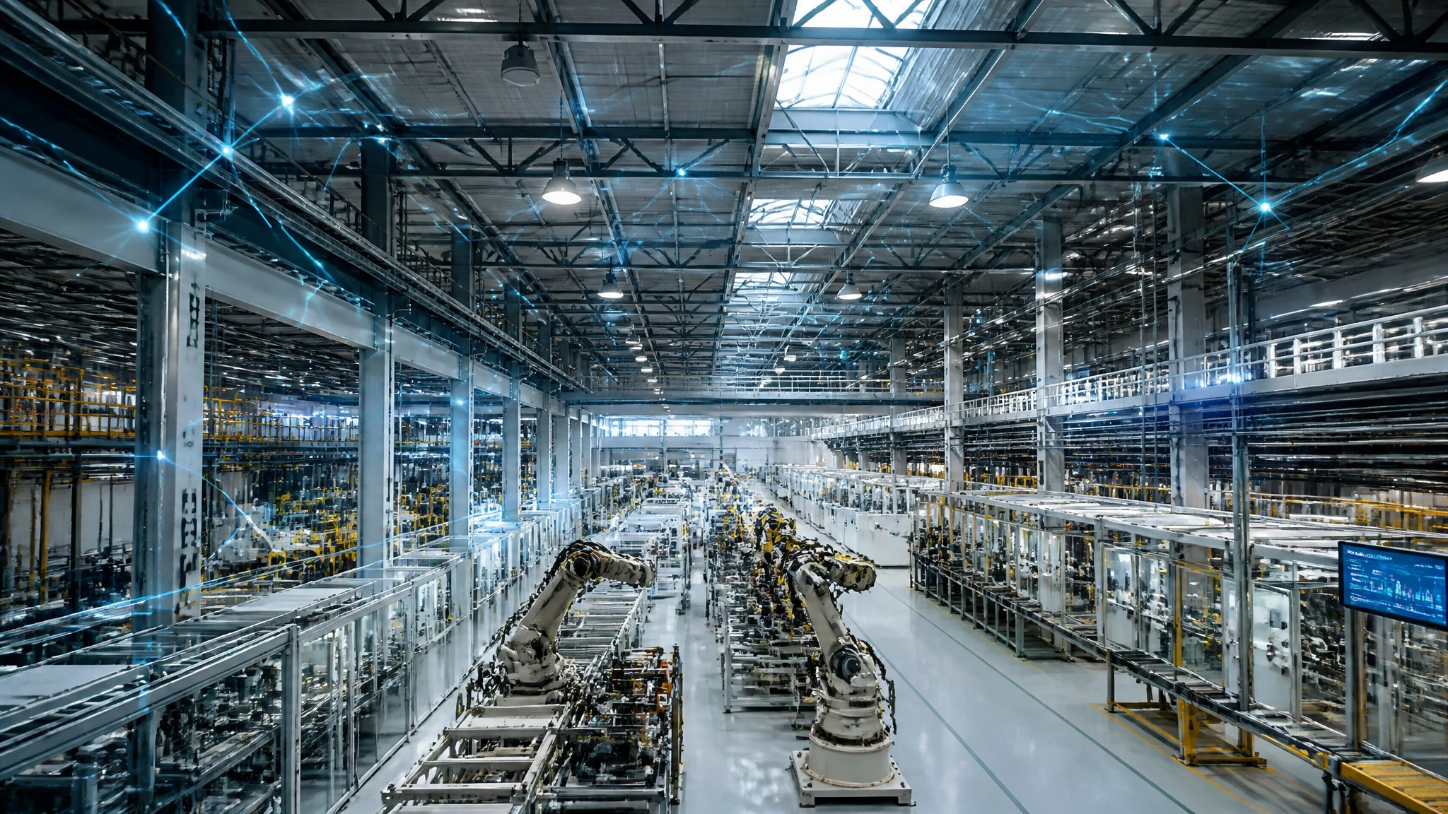
Deploying automated lighting controls in a factory environment requires combining multiple control strategies to maximize energy efficiency while maintaining strict workplace visual comfort standards.
Daylight Harvesting: Continuously modulates fixture output based on natural daylight contribution entering skylights or windows to maintain constant task surface illuminance.
Occupancy & Vacancy Sensing: Automatically dims or deactivates luminaires when worker motion is no longer detected in specific factory bays or aisleways.
Task Tuning (High-End Trim): Sets a permanent artificial ceiling on maximum fixture power output to align precisely with required task lighting specifications, compensating for initial luminaire over-design.
Automated Load Shedding: Curtails non-critical lighting loads by 20% to 30% during peak electrical utility tariff windows or facility power surges.
Time-Clock Scheduling: Automates shift-based lighting scene transitions across plant operational hours, switching off non-essential zones during plant shutdowns.
Selecting the appropriate driver protocol determines system responsiveness, dimming resolution, and diagnostic reporting capabilities across plant floors.
| Protocol Parameter | 0-10V Analog Dimming | DALI-2 Digital Protocol | Pulse-Width Modulation (PWM) |
| Signal Type | DC Voltage (0V to 10V) | Bi-directional Digital Bus | Pulsed High-Frequency Signal |
| Control Topology | Single-Directional (Broadcast) | Multi-Master Bi-Directional | Single-Directional |
| Addressing Capability | Group/Wiring Channel Level | Individual Fixture (64 per bus) | Circuit Level |
| Dimming Range | 10% to 100% (Standard) | 0.1% to 100% (Logarithmic) | 1% to 100% |
| Diagnostic Feedback | None (Control Only) | Real-time Power, Temp, Faults | None |
| Wiring Requirements | 2-Wire Dedicated DC Pair | 2-Wire Polarity-Free Bus | 2-Wire Dedicated Output |
| System Scalability | Limited by Voltage Drop | Highly Scalable via Gateways | Limited to Local Driver |
Plant engineers and financial controllers evaluate automated lighting controls using rigorous mathematical models to predict energy savings, thermal offsets, and lumen depreciation curves.
The total illuminance on a factory task surface is the sum of natural daylight contribution and controlled artificial luminaire output:
Formula: E_total = E_daylight + (P_dim * E_max)
Where:
E_total: Target total illuminance on the work surface (in Lux, e.g., 500 Lux).
E_daylight: Real-time natural daylight illuminance measured by photodiode sensors (in Lux).
P_dim: Dynamic dimming power percentage calculated by the controller (ranging from 0.01 to 1.00).
E_max: Maximum artificial illuminance generated by luminaires at 100% full power (in Lux).
To maintain constant target illuminance (E_total), the controller continually recalculates required dimming power:
Control Adjustment Formula: P_dim = (E_target - E_daylight) / E_max
If natural daylight (E_daylight) exceeds or equals E_target, P_dim drops to 0 (or minimum driver threshold), completely eliminating artificial lighting energy consumption during daylight hours.
To calculate total annual electricity consumption for a facility equipped with an automated lighting controls system, engineers apply correction factors to baseline power loads:
Formula: Energy_Annual = Sum [ (P_installed * N_fixtures * F_occupancy * F_daylight * F_task * T_hours) / 1000 ]
Where:
Energy_Annual: Total annual electrical energy consumption (in kilowatt-hours, kWh).
P_installed: Nominal full-power wattage of each luminaire (in Watts, e.g., 200W).
N_fixtures: Total number of installed luminaires across the facility (e.g., 1,200 units).
F_occupancy: Occupancy factor (ratio of active operational time vs standby/vacant time, e.g., 0.65).
F_daylight: Daylight harvesting factor (ratio of required artificial power during daylight hours, e.g., 0.70).
F_task: Task-tuning high-end trim factor (e.g., 0.80 for an 80% power cap).
T_hours: Total annual facility operating hours (e.g., 8,760 hours for 24/7 continuous operation).
Consider a manufacturing plant operating 1,200 units of 200W high-bay fixtures continuously (8,760 hours/year) at an electricity tariff of $0.14 per kWh.
Uncontrolled Baseline Consumption:
Energy_Base = (200 * 1,200 * 1.0 * 1.0 * 1.0 * 8,760) / 1000 = 2,102,400 kWh/year
Annual Cost = 2,102,400 kWh * $0.14 = $294,336
Automated Lighting Controls Consumption:
Applying F_occupancy = 0.65, F_daylight = 0.70, and F_task = 0.80:
Combined Control Factor = 0.65 * 0.70 * 0.80 = 0.364 (63.6% reduction)
Energy_Controlled = (200 * 1,200 * 0.364 * 8,760) / 1000 = 765,273.6 kWh/year
Annual Cost = 765,273.6 kWh * $0.14 = $107,138
Direct Annual Financial Savings:
Annual Savings = $294,336 - $107,138 = $187,198 per year
Plant managers interested in analyzing real-world warehouse energy reduction figures can consult our detailed case breakdown on
Deploying automated lighting controls ensures industrial facilities maintain compliance with global energy codes, sustainability certifications, and workplace illumination standards.
ASHRAE Standard 90.1 & IECC (International Energy Conservation Code): Mandates automatic shutoff controls, occupancy setback thresholds, and daylight-responsive dimming in primary daylight zones for commercial and industrial buildings.
California Title 24, Part 6: Enforces mandatory multi-level astronomical time-clock scheduling and automatic demand response (ADR) capabilities. Requires occupant-sensing controls that reduce power by at least 50% in vacant areas with mounting heights under 12 meters.
EN 12464-1 (Europe - Lighting of Work Places): Defines strict workplace visual ergonomics. Mandates minimum maintained illuminance levels (e.g., 300 Lux for machining, 500 Lux for fine assembly) while capping Unified Glare Ratings (UGR < 22).
LEED v4.1 & BREEAM Certifications: Contributes up to 18 points under Energy and Atmosphere (EA) Credit: Optimize Energy Performance, while earning additional points under Indoor Environmental Quality (EQ) for advanced lighting controllability.
Industrial environments present hostile operational conditions including high ambient heat, airborne oil mists, heavy dust accumulation, mechanical vibration, and electrical voltage transients. Hardware selected for an industrial automated lighting controls system must meet rigorous structural and environmental ratings.
| Hardware Category | Recommended Technical Specification | Industrial Protection Function |
| High-Bay Motion Sensors | Dual-Tech (PIR + Microwave 5.8 GHz), 360° coverage up to 18m height | Eliminates false triggers from HVAC air currents and thermal plumes |
| Photodiode Photocells | Digital closed-loop sensor with IR-filtering glass lens, 1 to 10,000 Lux range | Prevents sensor drift caused by indirect wall reflections and dust accumulation |
| Control Gateways | Metal DIN-rail IP30/IP60 housing, Dual Ethernet ports, TPM 2.0 security chip | Protects against electrical noise, thermal stress, and network intrusion |
| Relay Controller Packs | Heavy-duty zero-crossing latching relays rated for 16A/20A inrush currents | Prevents contact welding caused by high LED driver initial inrush currents |
| Smart LED Drivers | Metal enclosure IP67 rated, 10kV surge protection, class P thermal protection | Maintains operational stability from -40°C to +70°C ambient temperatures |
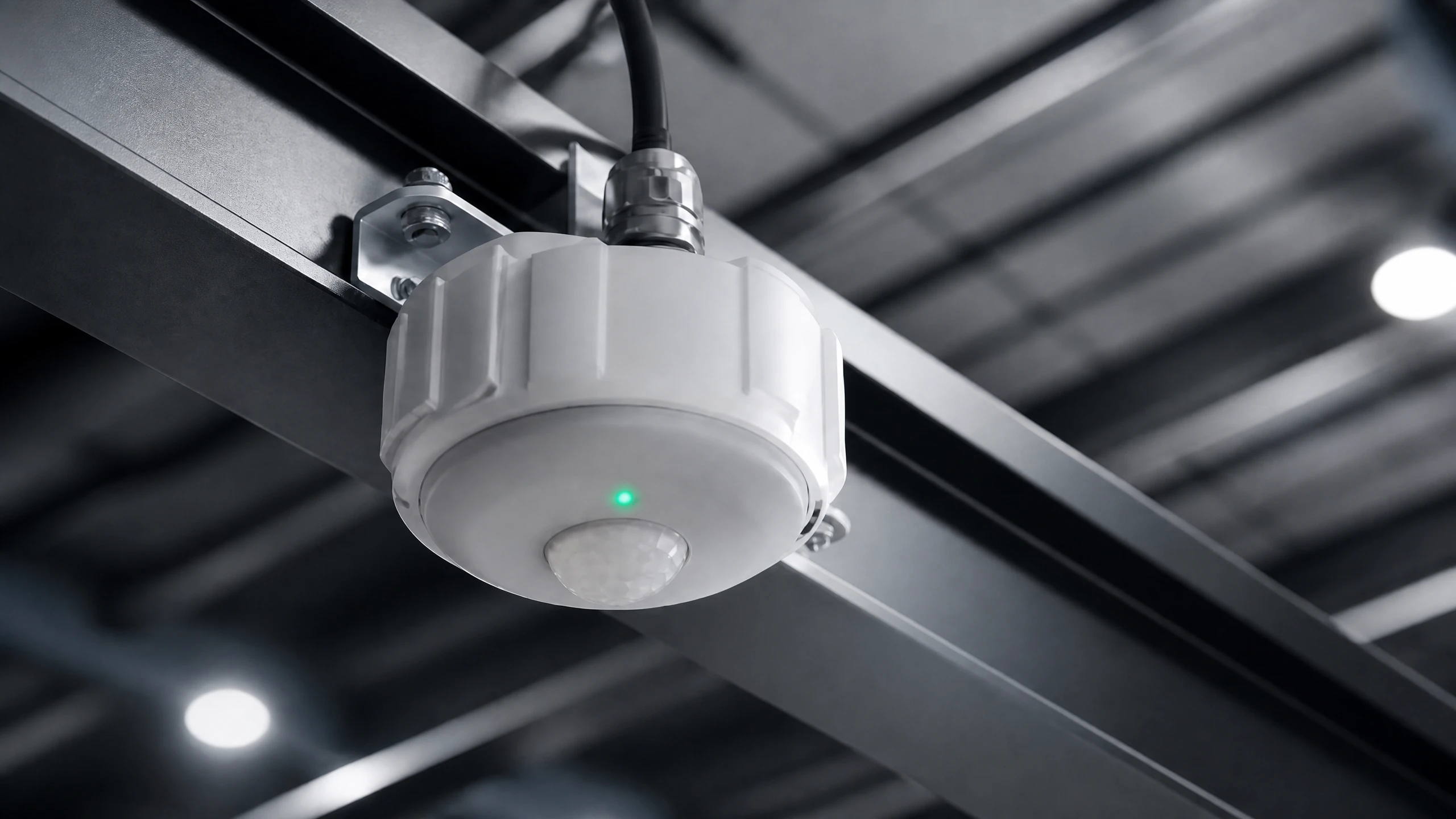
Successfully installing an automated lighting controls system without disrupting active manufacturing schedules requires following a structured 5-phase engineering protocol.
Phase 1: Photometric Audit and Baseline Mapping
Conduct field light measurements across all plant zones using calibrated lux meters. Map existing electrical feeds, daylight entry points, ceiling obstruction heights, and localized reflection factors.
Phase 2: Control Zoning and Network Architecture Design
Divide facility floors into functional control zones (e.g., Main Assembly Line, Staging Area, High-Racking Aisleways). Select control topologies (wired DALI-2 vs wireless BLE mesh) and map sensor coverage footprints to eliminate blind spots.
Phase 3: Physical Installation and Wiring Execution
Mount industrial sensors, control gateways, and smart drivers. Ensure proper separation between high-voltage AC lines (100V–480V) and low-voltage control signals (0-10V / DALI bus) to prevent electromagnetic induction noise.
Phase 4: System Provisioning and Sensor Calibration
Assign cryptographic network keys to all wireless nodes or map DALI short addresses. Calibrate daylight harvesting photodiodes by taking baseline lux readings at night and during peak daylight hours. Set occupancy hold times and dimming thresholds.
Phase 5: Post-Occupancy Verification and Fine-Tuning
Audit system performance during live production shifts. Verify that light transitions do not cause visual discomfort for operators or forklift drivers. Review gateway energy logs to confirm targeted kilowatt-hour savings are achieved.
To explore how these implementation steps transform safety and productivity on the shop floor, read our technical review on
Investing in automated lighting controls represents a capital expenditure (CapEx) that delivers substantial long-term operational expenditure (OpEx) reductions. The 10-year Total Cost of Ownership model below compares three facility lighting strategies:
Plant Size: 50,000 square meters heavy equipment manufacturing facility.
Luminaire Quantity: 1,200 High Bay Luminaires (200W nominal output).
Operating Hours: 24 hours/day, 365 days/year (8,760 hours/year).
Electricity Rate: $0.14 per kWh.
HVAC Cooling Efficiency Factor: COP 3.0 (every 3 kWh of lighting energy reduced saves 1 kWh of cooling energy).
| Cost / Performance Metric | Legacy Metal Halide (400W) | Uncontrolled LED High Bay (200W) | Full Automated Lighting Controls System |
| Connected Load per Fixture | 440W (with ballast) | 200W | 200W (72.8W effective with controls) |
| Total Connected System Load | 528 kW | 240 kW | 87.36 kW (Effective Average Load) |
| Annual Electricity Consumption | 4,625,280 kWh | 2,102,400 kWh | 765,273 kWh |
| Annual Electricity Cost | $647,539 | $294,336 | $107,138 |
| Annual HVAC Cooling Cost Factor | $215,846 | $98,112 | $35,712 |
| Annual Maintenance & Lamp Replacement | $42,000 | $8,500 | $1,500 |
| Total Annual Operational Cost | $905,385 | $400,948 | $144,350 |
| Initial Hardware & Installation CapEx | Baseline | $180,000 | $245,000 |
| 10-Year Operating Expense (OpEx) | $9,053,850 | $4,009,480 | $1,443,500 |
| 10-Year Total Cost of Ownership (TCO) | $9,053,850 | $4,189,480 | $1,688,500 |
| 10-Year Net Savings vs. Uncontrolled LED | Baseline | Baseline | $2,500,980 |
Incremental Capital Investment for Controls: $65,000 ($245,000 controlled LED system vs $180,000 uncontrolled LED system).
Annual Operating Cost Reduction: $256,598 per year ($400,948 vs $144,350).
Simple Payback Period: 3.04 months.
10-Year Return on Investment (ROI): 3,747%.
Deploying an automated lighting controls system yields complete capital payback in approximately 3 months, generating ongoing multi-million dollar operational savings across the remaining lifespan of the hardware.
LumiEasy industrial automated lighting controls use IP65 and IP67 ruggedized sensor enclosures with hydrophobic lenses and anti-static optical covers. Optical photodiodes incorporate software digital filtering algorithms that detect gradual dust accumulation over time, automatically recalibrating light gain thresholds to prevent sensor drift without requiring frequent manual cleaning.
Yes. LumiEasy provides compact wireless automated lighting controls modules that connect directly to standard 0-10V or DALI drivers via Zhaga Book 18 or ANSI C136.41 7-pin NEMA receptacles. These plug-and-play controllers instantly convert existing standalone LED high bays into intelligent, wireless mesh nodes without pulling new control wiring through high-bay conduits.
LumiEasy automated lighting controls feature a decentralized edge architecture with integrated "Fail-Safe On" hardware relays. If a sensor, control gateway, or wireless network node experiences a hardware failure or communication loss, the luminaire driver instantly defaults to 100% full brightness, ensuring continuous plant floor illumination and uninterrupted worker safety.
Upgrading your manufacturing plant with an intelligent control infrastructure reduces electrical energy overhead, lowers HVAC cooling loads, and extends luminaire operational lifespans.
To review complete hardware data sheets, request photometrical layout simulations, or consult with our automation engineers,


)
)
)
)

+86 15899791249

+86 755 2955 3313


Address: Huafeng No.1 Science and Technology Park, Sanwei, Bao'an District, Shenzhen, Guangdong, China.
