

Time:2026-08-07
When a light fixture fails on a 12-meter ceiling in a busy factory, fixing it is never simple or cheap. Plant managers must hire technicians, rent scissor lifts, and halt production lines. A simple bulb or driver change can quickly cost thousands of dollars in lost time and extra labor.
To solve this problem, industrial lighting is shifting from reactive repairs to smart predictive maintenance. The key behind this shift is D4i—the smart extension of the DALI-2 standard created by the Digital Illumination Interface Alliance (DiiA).
D4i transforms LED drivers from basic power units into intelligent data nodes. By storing critical hardware, energy, and diagnostic data inside the driver, D4i allows plant managers to monitor fixtures remotely and fix problems before they cause downtime.
This technical dali d4i maintenance reporting data standards guide explains how D4i data structures work, how to program them in your factory, and how to build self-diagnostic luminaires for industrial clients.
To understand D4i maintenance reporting, you first need to see how the DALI protocol (IEC 62386) has evolved over time. Standard legacy DALI-1 provided simple broadcast dimming with minimal feedback. DALI-2 introduced standardized two-way digital communication between drivers, sensors, and controllers across a lighting network.
However, D4i focuses specifically on the data inside the luminaire.
D4i turns the LED driver into an active data hub. It introduces integrated bus power (DALI Part 250), luminaire asset data (DALI Part 251), real-time energy reporting (DALI Part 252), and diagnostic maintenance tracking (DALI Part 253). The driver extracts operational information and passes it to wireless control nodes (such as Zhaga Book 18 or NEMA sockets) and central Building Management Systems (BMS). Because D4i uses standardized memory structures, facility managers can manage fixtures from different suppliers using a single cloud interface.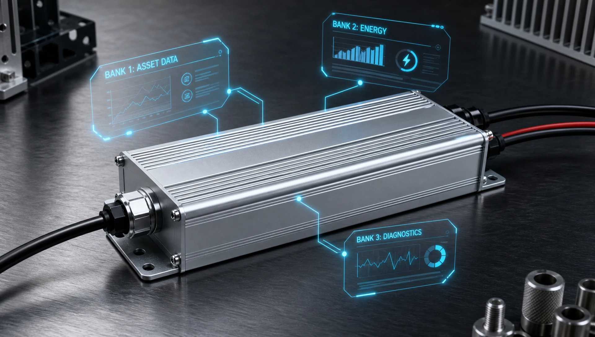
D4i maintenance reporting relies on three core DiiA specifications: DALI Part 251, Part 252, and Part 253. Each specification maps directly to a specific Memory Bank inside the driver's microcontroller:
Memory Bank 0: Stores DALI Part 102 system information (GTIN, serial numbers, firmware versions).
Memory Bank 1: Stores DALI Part 251 luminaire asset data (model specifications, power ratings, color rendering, light output).
Memory Bank 2: Stores DALI Part 252 energy reporting data (real-time wattage, cumulative energy usage, power factor).
Memory Bank 3: Stores DALI Part 253 diagnostics and maintenance logs (runtime hours, operating temperatures, thermal stress history, failure logs).
DALI Part 251 lets original equipment manufacturers (OEMs) write asset identification data into the driver during factory assembly. When technicians install the fixture, the central software reads Memory Bank 1 and automatically inventories the light.
Key data stored in Memory Bank 1 includes:
GTIN (Global Trade Item Number): A unique 14-digit product identifier.
Electrical Input Specs: Voltage range (e.g., 120V–277V), AC line frequency, and wattage ratings.
Light Performance Parameters: Output lumens, Correlated Color Temperature (CCT), Color Rendering Index (CRI), and light distribution type.
Factory Identification: OEM company code, manufacturing plant location, and housing color.
This digital label replaces physical stickers that degrade over time. If a fixture breaks, technicians can check the exact model and part numbers from their computer screen before heading to the warehouse.
Factory managers need accurate energy tracking to lower operational costs and meet ISO 50001 standards. DALI Part 252 standardizes how LED drivers calculate and report power usage without needing external sub-meters or extra wiring.
The driver continuously updates key power metrics in Memory Bank 2:
Active Power (Watts): Real-time power draw updated instantly during dimming.
Active Energy (kWh): Total electricity consumed over the luminaire's lifetime.
Apparent Power (VA) and Power Factor (PF): Critical values for evaluating plant grid efficiency and avoiding power utility penalties.
AC Input Voltage (V) and Line Current (mA): Helps identify line voltage drops, power surges, or poor power quality across long factory wiring runs.
D4i drivers deliver active power measurement accuracy within +/- 5% for loads above 15W, with high-tier drivers reaching +/- 2% accuracy.
DALI Part 253 is the backbone of predictive maintenance. It tracks operational stress, thermal health, and component failure logs to alert technicians before a fixture fails completely.
| Memory Address | Saved Parameter Description | Data Format / Unit |
| 0x0A - 0x0D | Driver Total Operating Time | Hours (32-bit Integer) |
| 0x0E - 0x11 | LED Module Total Operating Time | Hours (32-bit Integer) |
| 0x12 - 0x13 | Total Driver Start Cycles | Power-on Count |
| 0x14 - 0x15 | Current Internal Temperature | Degrees Celsius (°C) |
| 0x16 - 0x17 | Maximum Lifetime Temperature | Degrees Celsius (°C) |
| 0x18 - 0x19 | Over-Temperature Event Counter | Count |
| 0x1A - 0x1B | Time Spent in Thermal Derating | Hours |
| 0x1C - 0x1F | Light Source Failure Counter | Open/Short Circuit Events |
By querying these registers, software can spot early warning signs:
Overheating: If the internal temperature stays above 85°C, dust may be blocking the heat sink or ambient room temperatures are too high.
LED Aging: Comparing operating hours against LED lifespan ratings helps managers schedule group replacements before light levels drop below workplace safety limits.
Unstable Power Grid: High start-cycle counts combined with short runtimes indicate unstable electrical circuits or failing breakers.
For more information on hardware integration and smart node setup, read our complete
To ensure D4i data remains accurate in the field, luminaire factories must lock Memory Bank 1 after programming. This prevents end users or installation software from overwriting factory data by mistake.
Connect Driver to Programming Software: Plug the driver into an automated USB-to-DALI test bench.
Send Unlock Key: Write the OEM factory security password to Register 0x02.
Write Luminaire Asset Parameters (Part 251): Program the GTIN into Bytes 0x03–0x10, Serial Number into Bytes 0x11–0x1A, along with CCT, CRI, output lumens, and rated voltage.
Lock Memory Bank 1: Write 0xFF to Register 0x02 to lock data permanently.
Verify Compliance: Run an automated read-back test to confirm data accuracy and lock status.
Register 0x02 inside Memory Bank 1 acts as the security lock:
Unlocked State (0x00 or OEM Key): Factory programming rigs can write and edit asset information.
Locked State (0xFF): Before the luminaire leaves the factory, the system writes 0xFF to Register 0x02. Once locked, Memory Bank 1 becomes read-only over standard DALI network interfaces.
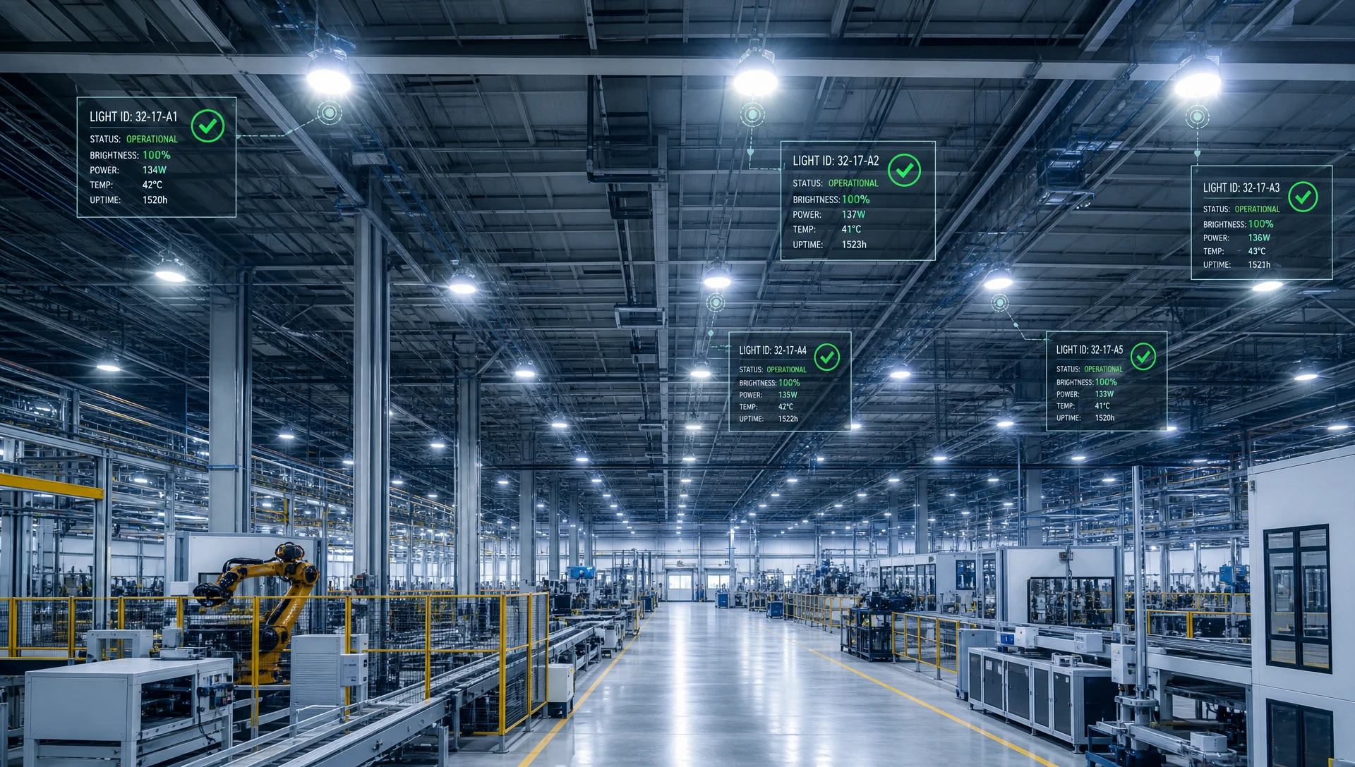
D4i diagnostic data delivers clear financial savings for industrial facilities compared to older reactive maintenance methods:
Instant Fault Detection: Rather than waiting for a factory worker to report a broken light, central software receives instant alerts when an anomaly occurs.
Remote Fault Diagnosis: Instead of riding a scissor lift up to inspect a ceiling fixture, technicians diagnose issues from a computer console.
Slashed Service Trips: Older methods require two trips (one to inspect and diagnose, and one to bring back parts and repair). D4i allows a single direct repair trip because the replacement part is identified in advance.
Zero Production Downtime: Repairs are scheduled during planned factory maintenance windows rather than causing unexpected line stoppages.
With D4i diagnostic reporting, the software receives an automated alert with the precise failure code (e.g., Bank 3 Register 0x1C: LED Open Circuit or Bank 3 Register 0x14: Over-Temperature Fault). Technicians grab the exact spare part on their first trip, cutting labor time in half.
To learn how predictive data lowers factory maintenance budgets, explore our guide on how
 5. Troubleshooting Common D4i Data Errors
During factory programming or field setup, technicians may encounter reading or writing errors across D4i memory banks. Use this quick guide to solve common technical issues:
| Common Error | Likely Cause | Simple Solution |
| Memory Bank 1 Read Error (NACK) | The memory bank is turned off or has an invalid address. | Check Register 0x00 in Memory Bank 0 to verify memory support. Confirm DALI command 223 formatting. |
| Energy Data Reads 0 Watts | The electrical load is below the driver's sensing threshold (< 5%). | Turn on the light and dim above 10%. Verify the driver supports DALI Part 252 for low-power tracking. |
| Jumbled or Missing GTIN Strings | Incorrect ASCII formatting used during factory programming. | Format the GTIN as a 14-digit numerical string with leading zeros per DALI Part 251 rules. |
| Unrealistic Temperature Reading | Internal NTC temperature sensor mapping offset error. | Update the driver firmware to fix the lookup table. Make sure ambient room temp is between -40°C and +85°C. |
| Lock Byte Rejection | Using an incorrect security password on Register 0x02. | Verify the OEM manufacturer password. Reset the driver to factory defaults using certified DALI software. |
Here is how standard DALI-2 drivers compare to full D4i-compliant drivers for commercial and industrial lighting:
| Key Feature | Standard DALI-2 Driver | DALI D4i Driver |
| Core Function | Basic dimming, switching, and scene control | Real-time energy, asset, and diagnostic data |
| Bus Power Supply (Part 250) | Needs external power supply unit | Built-in (Provides 52 mA to 250 mA bus power) |
| Asset Tracking (Part 251) | Not supported | Built-in (Memory Bank 1 asset logging) |
| Energy Metering (Part 252) | Not supported | Built-in (Memory Bank 2 active power logging) |
| Diagnostics (Part 253) | Not supported | Built-in (Memory Bank 3 failure tracking) |
| Smart Sensor Integration | Requires separate power supply wiring | Plug-and-play via Zhaga Book 18 or NEMA sockets |
| Best Uses | Basic indoor office dimming | Factories, warehouses, high-bays, and smart cities |
If you are upgrading an industrial fixture line to meet D4i standards, follow these five practical steps:
Select D4i-Certified Components: Choose drivers that support DALI Parts 250, 251, 252, and 253.
Install Standardized Sockets: Add a Zhaga Book 18 or NEMA 7-pin socket to your fixture housing.
Setup Factory Line Flashing: Connect USB-to-DALI tools to your production testing station.
Lock Memory Bank 1: Write 0xFF to Register 0x02 to protect asset data before packing.
Test Field Compatibility: Connect a wireless control node and test energy readings on cloud software.
Adopting DALI D4i maintenance reporting standards turns simple lighting fixtures into smart digital assets. By configuring DALI Part 251 asset tracking, Part 252 energy metering, and Part 253 failure diagnostics, lighting manufacturers can deliver reliable, low-maintenance lighting systems built for demanding factory environments.
Ready to upgrade your industrial light fixtures with certified D4i drivers and smart sensor-ready controls? Our engineering team is here to help you with driver configuration, custom stackup advice, and prototype development. Contact our engineering team today through the official
A1: DALI Part 253 tracks key operational metrics—such as driver temperature, total operating hours, thermal stress events, and LED open/short circuits—directly inside driver memory. Central software uses this data to alert managers before complete failures occur. Technicians receive precise fault details, allowing them to bring the correct replacement parts on their first trip and eliminating costly diagnostic visits.
A2: Yes. LumiEasy offers automated factory programming services during production. We write your GTIN, nominal voltage ratings, light output specs, CCT, CRI, and serial numbers directly into DALI Part 251 (Memory Bank 1). We then apply the memory lock byte so your asset details stay secure throughout the product's lifespan.
A3: DALI Part 252 energy reporting is built directly inside the LED driver. It measures real-time active power (W), energy consumption (kWh), and power factor without needing external power meters or extra wiring. The driver sends accurate energy logs straight to your BMS software, making ISO 50001 energy audits easy and affordable.


)
)
)
)

+86 15899791249

+86 755 2955 3313


Address: Huafeng No.1 Science and Technology Park, Sanwei, Bao'an District, Shenzhen, Guangdong, China.
