

Time:2026-07-17
Centralized emergency lighting monitoring becomes more useful when it feeds the BMS with clear, location-based status and test data. The BMS can show alarms, route them to the right team, and preserve an audit trail. The emergency lighting system should keep its local safety functions if the BMS or network goes offline.
centralized emergency lighting monitoring
The existing centralized emergency lighting monitoring guide explains the core functions of monitoring systems: scheduled testing, fault alerts, battery status, digital records, and multi-site visibility.
Facility teams then need to decide where emergency lighting data belongs in the daily operating workflow.
A BMS integration can give facility teams one place to see critical building alarms. It can connect an emergency lighting fault with a floor, zone, room, asset number, and maintenance task. That context helps a technician decide what to check before visiting the site.
The integration also supports a clear division of responsibility:
The emergency lighting system monitors fixtures, batteries, charging circuits, tests, and local faults.
The gateway or integration layer translates that information into a format the BMS can read.
The BMS displays alarms, trends, and system health beside other building data.
The maintenance team responds to the alarm, records the repair, and closes the event after a successful retest.
The BMS needs selected device values that help the facility team understand risk, priority, and location.
Data group | Useful BMS points | Why it helps |
System health | System normal, system fault, gateway health | Shows whether the monitoring service can report current data |
Fixture status | Lamp fault, fixture fault, device offline | Identifies an asset that needs inspection |
Battery and charging | Battery fault, low battery, charging fault, battery replacement due | Helps the team plan service before a power failure exposes the problem |
Test status | Function test result, duration test result, test in progress, last test time | Gives the team a view of test completion and failures |
Communication | Controller offline, network fault, BMS link fault | Separates a data path problem from a fixture problem |
Asset context | Building, floor, zone, room, device ID, fixture type | Lets the technician find the correct device |
Maintenance state | Alarm acknowledged, work order open, repair complete, retest passed | Connects monitoring with the service workflow |
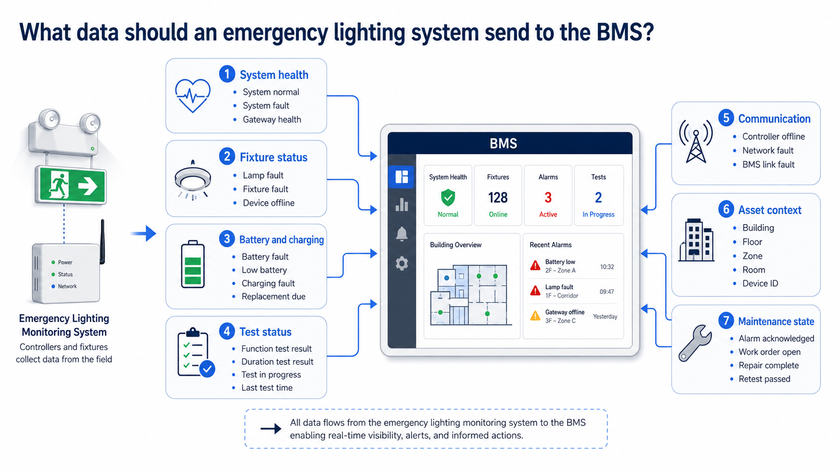
Each point should carry a timestamp and a stable asset ID. A generic alarm such as “emergency lighting fault” forces the technician to search. A point such as “Battery fault, Level 2, East Stair 02, EL-024, 09:42” supports a faster response.
A centralized emergency lighting monitoring system usually has four layers:
Emergency lighting devices collect local operating, battery, charging, and test information.
Controllers and gateways collect device data across a wired or wireless network.
The monitoring platform stores events, shows device status, and manages test records.
The BMS integration layer passes selected alarms and status points into the building operator's interface.
The connection between the monitoring platform and the BMS may use BACnet/IP, Modbus TCP, MQTT, a REST API, or a vendor-specific interface. The right option depends on the existing BMS, cybersecurity policy, gateway capability, and project specification.
The LumiEasy network setup guide already covers network topology, wired versus wireless communication, device compatibility, and data security. A BMS project adds one more requirement: the integration must preserve the meaning of each alarm.
For example, the BMS should distinguish these conditions:
A lamp or LED fault
A battery or charging fault
A failed functional or duration test
A fixture that stopped communicating
A gateway that stopped communicating
A lost connection between the monitoring platform and the BMS
If the integration merges these conditions into one alarm, the operator loses the information needed for triage.
The BMS should supervise emergency lighting status. It should not become the only system that can keep emergency lighting ready for use.
The emergency lighting control system should retain the local functions required by the project design, including emergency operation, battery support, test routines, and fault indication. If the BMS server, network switch, gateway, or cloud connection fails, the emergency lighting equipment should continue to perform its intended local function. The BMS should report the communication loss as a separate event.
This separation also helps the project team test the right failure modes. A BMS screen can show “normal” while a gateway has stopped receiving current device data. The monitoring system therefore needs a communication timeout, heartbeat, or equivalent supervision method.
IEC 62034 covers performance and safety requirements for components used in automatic test systems for battery-powered emergency escape lighting. Its listed requirements include intercommunication failure, component failure, software failure, functional tests, and duration tests. Use the applicable edition and local requirements during design and approval. See the IEC 62034 publication page.
Alarm volume affects response quality. A BMS integration that forwards every device event to every user can create alert fatigue.
Use three practical alarm levels as a starting point.
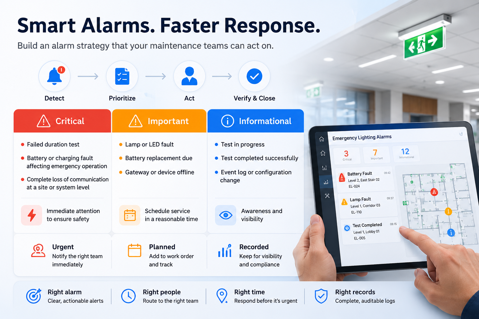
Use this level for a failed duration test, a battery fault that affects emergency operation, a charging fault, or a system condition that may leave a required area without emergency lighting.
Send the alarm to the responsible maintenance group. Include the location, asset ID, fault code, timestamp, and last successful test.
Use this level for a lamp fault, a fixture fault, a device offline condition, or a battery nearing replacement. Create a maintenance task with a target response time that matches the site's risk assessment and service agreement.
Use this level for a gateway offline event, a controller communication fault, a stale data condition, or a lost BMS connection. The team should know that the display may not represent current field status.
The LumiEasy guide to emergency lighting control monitoring requirements discusses automated testing, centralized control panels, fault detection, backup power monitoring, compliance, and scalability. The BMS layer should expose those results without hiding the original fault source.
Commissioning should test the field devices and the data path. A green BMS screen can still hide a reporting failure.
Use this checklist during commissioning:
Confirm the asset list. Match each fixture, controller, gateway, and BMS point with the approved drawings and location schedule.
Check normal status. Confirm that the monitoring platform and BMS show the same system state.
Run scheduled tests. Verify that function and duration test results reach the monitoring platform and the BMS with the correct timestamps.
Create test faults. Use approved test methods to confirm battery, charging, lamp, fixture, and communication alarms.
Check alarm routing. Confirm that each alarm reaches the right user group and carries the required location and asset information.
Test the data path. Disconnect the gateway or BMS link under a controlled procedure. Confirm that the monitoring system records the loss and that emergency lighting retains local operation.
Verify records and reports. Export test history, fault history, repair status, and retest results. Store the final point list and cause-and-effect record with the handover documents.
The project team should record the test method, expected result, actual result, date, responsible person, and corrective action. This turns commissioning into evidence that another facility team can review later.
Monitoring creates value when the team closes the loop. A useful workflow looks like this:
Alarm received -> fault triaged -> work order assigned -> repair completed -> retest performed -> record closed
The monitoring platform or BMS should retain the original event. The maintenance record should add the technician's action, replaced part, completion time, and retest result.
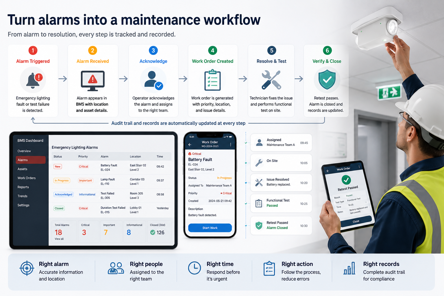
This structure helps a facility manager answer four questions during a review:
Which device failed?
How long did the fault remain open?
What action did the technician take?
Did the device pass a test after the repair?
The result supports maintenance planning as well as safety documentation. It can reveal repeated battery failures, devices that lose communication, and zones that need a network or power review.
Yes, if the retrofit design covers device compatibility, network coverage, gateway placement, cybersecurity, and fallback operation.
Wireless monitoring can reduce new control wiring in an existing building. The design team still needs a site survey that checks wall and ceiling construction, equipment rooms, metal obstructions, fire-rated areas, power availability, and access for testing.
For an industrial or warehouse project, a wireless gateway can connect a local lighting network to a BMS or IoT platform. The LumiEasy wireless BLE lighting control guide explains how gateways support centralized monitoring, remote management, and external platform integration. The commercial retrofit guide provides related context for existing commercial spaces.
Use a phased retrofit when the building contains several systems or occupied areas. Start with one floor or risk zone, prove the alarm mapping, then extend the design to the rest of the site.
An integrated dashboard complements the applicable emergency lighting design, inspection, testing, maintenance, and record-keeping requirements.
For UK projects, BSI lists BS 5266-1:2025 as the current code of practice for emergency lighting of premises. BSI describes the standard as covering the design, provision, and use of emergency lighting, including routine inspections, tests, service, and repair. See the BSI BS 5266 page.
Projects in other countries should follow the adopted local code, product requirements, fire strategy, risk assessment, and authority having jurisdiction. The owner, designer, emergency lighting specialist, and BMS integrator should agree on the test schedule and records before installation.
Yes. A gateway, API, or protocol interface can pass selected emergency lighting status, test results, fault alarms, and communication events to a BMS. The project team must confirm compatibility and define the point list before installation.
No. The BMS can provide a shared operator interface, but the emergency lighting system should keep the local monitoring, test, fault indication, and emergency operation required by the project design.
Common options include BACnet/IP, Modbus TCP, MQTT, REST APIs, and vendor interfaces. The selected protocol should match the BMS, gateway, network policy, cybersecurity controls, and maintenance capability.
The emergency lighting system should continue its intended local operation. The monitoring system should record the lost connection, and the BMS should show a separate communication alarm when the link returns or when supervision detects stale data.
It can be useful when the site already operates a BMS or when the owner needs one maintenance view. A small building with few devices may use standalone self-testing equipment and local records instead. The decision depends on device count, building layout, staffing, and documentation needs.
Centralized emergency lighting monitoring gives facility teams the field data they need. BMS integration makes that data part of the daily maintenance workflow.
The strongest design keeps local emergency operation independent, maps each alarm to a clear asset and location, supervises the communication path, and records the repair and retest. That approach gives building owners and facility managers a useful view of emergency lighting readiness without turning the BMS into a single point of failure.
LumiEasy can help project teams plan the monitoring architecture, gateway connection, alarm point list, wireless retrofit approach, and commissioning workflow for commercial and industrial buildings. Contact LumiEasy to discuss your building layout and integration requirements.
Related news
Emergency lighting monitoring network setup
Emergency lighting control monitoring requirements
Centralized emergency lighting compliance




+86 15899791249

+86 755 2955 3313


Address: Huafeng No.1 Science and Technology Park, Sanwei, Bao'an District, Shenzhen, Guangdong, China.
